
OC-192/STM-64 SERDES Transceiver module Specification; OAT1041x-V5-z-yy
Document NO: QPS-0302-020
Rev. DRAFT 0.5
OKI Electric Industry Co., Ltd Optical Components Company
OKI Electric Industry Co., Ltd Optical Components Company
OKI Electric Industry Co., Ltd Optical Components Company
OKI Electric Industry Co., Ltd Optical Components Company
1
OKI Confidential
OAT1041x-V5-z-yy(for 12km)
OC-192/STM-64 SERDES Transceiver Module
Modification History
Rev. Date Originator
Comment
DRAFT0.1 Aug.16.2002 T.Itou
DRAFT0.2 Sep.05.2002 T.Itou
DRAFT0.3 Sep.25.2002 T.Itou
Revision of Absolute maximum of VEE
DRAFT0.4 Oct.2.2002 T.Itou
Additional of I2C diagnostic monitor
DRAFT0.4 Oct.17.2002 T.Itou
Change of Distance
Features ;
�
10G SFF Transceiver
�
SONET/SDH 9.953Gbps operation
SR-1/I64.1 @ OAT1041x-V5-A-yy
�
Support 10.3Gbps(10GbE), 10.66Gbps(FEC)
and 10.7Gbps(OTN) rate
�
Wavelength : 1310nm band
�
Transmission Distance :
12km(40ps/nm) @OAT1041x-V5-A-yy
�
Dispersion Penalty : <1dB
�
16-bit parallel 622.08Mbps(equivalent FEC rate)
LVDS data interface
�
SERDES Timing compliant with OIF1999.102.8
SFI-4 interface
�
Jitter filter built-in (OAT1041x-V5-C-yy, Multi-rate
type removes)
�
TxREFCLK frequency of 622MHz is standard.
(OAT1041x-V5-C-yy, Multi-rate type removes)
�
Compact size: 50.8 x 76.2 x 11.5 (mm)
�
Supply voltage : +3.3V , +1.8V and -5.2V
�
Low power consumption: <4.8W max.(3.8W typ.)
�
I2C compatible bus for simple status data monitor
Application ;
�
Metro network SONET/SDH system
�
10 Gigabit Ethernet system
�
Forward Error Correction system
�
Optical Transport Network (OTN) System
Document Number: QPS-0302-020
Revision: DRAFT 0.5
DATE: Oct.17.2002
Author: T.ITOU
Project Manager: T. ITOU

OC-192/STM-64 SERDES Transceiver module Specification; OAT1041x-V5-z-yy
Document NO: QPS-0302-020
Rev. DRAFT 0.5
OKI Electric Industry Co., Ltd Optical Components Company
OKI Electric Industry Co., Ltd Optical Components Company
OKI Electric Industry Co., Ltd Optical Components Company
OKI Electric Industry Co., Ltd Optical Components Company
2
OKI Confidential
1.
1.
1.
1.
Block diagram
LsENABLE
TxDIN[0:15]P/N
TxPICLKP/N
OC-192
Optical Output
TxLOCKERR
TX E-O
Driver
APC
TxREFCLKP/N
TxPCLKP/N
MUX
with CMU
TxRESET
TxREFSEL
TxMCLKP/N
RxPOCLKP/N
RxDOUT[0:15]P/N
RxREFCLKP/N
RxLOCKERR
OC-192
Optical Input
RxPOWMON
RX O-E
CDR
with DEMUX
RxLCKREF
RxPOWALM
RxMCLKP/N
LsBIASMON
LsPOWMON
LsPOWALM
LsBIASALM
TxRATESEL0/1
TxFIFORES
RxMUTEPOCLK
RxMUTEMCLK
RxMUTEDOUT
RxRATESEL0/1
16
16
RxREFSEL
Opt Mon
+3.3V +1.8V -5.2V GND
TxFIFOERR
Serial
Monitor
I2CCLOCK
I2CCLOCK
TxREFSEL,TxRATESEL0/1 are available for multi-rate type, OAT1041x-V5-C-yy.
Figure 1 Block diagram
OC-192/STM-64 SERDES Transceiver module Specification; OAT1041x-V5-z-yy
Document NO: QPS-0302-020
Rev. DRAFT 0.5
OKI Electric Industry Co., Ltd Optical Components Company
OKI Electric Industry Co., Ltd Optical Components Company
OKI Electric Industry Co., Ltd Optical Components Company
OKI Electric Industry Co., Ltd Optical Components Company
3
OKI Confidential
2.
2.
2.
2.
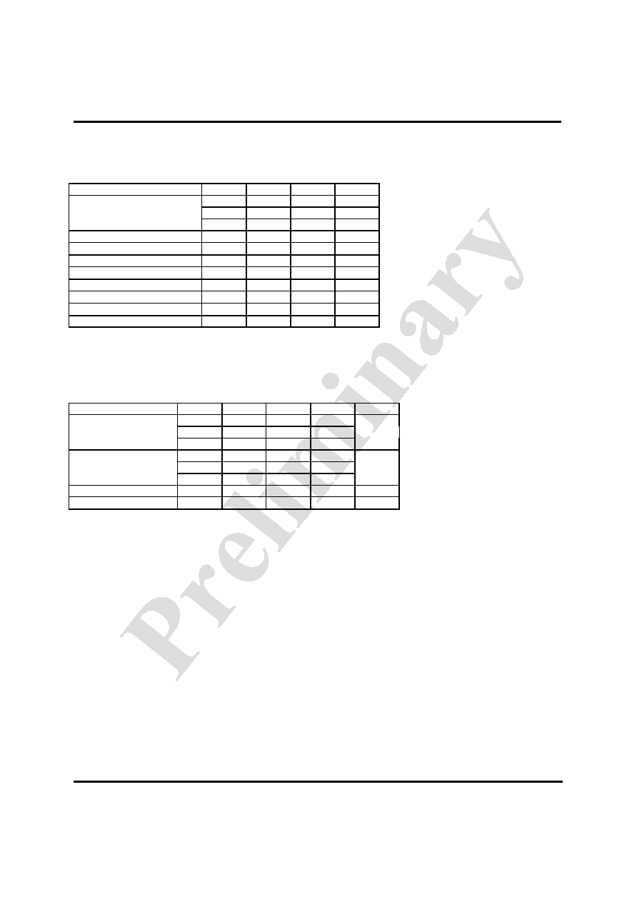
Absolute Maximum Ratings
Stresses in excess of the Absolute Maximum Ratings can cause permanent damage to the device.
Table 2 Absolute Maximum Ratings
Parameter Symbol
Min.
Max.
Units
V
DD1
-0.5 3.6 V
V
DD2
-0.5 2.0 V
Supply Voltage
V
EE
-6.0 +0.5 V
LVDS input pin
0 2.7 V
LVTTL input pin
0 3.6 V
LVTTL output sink current
50 mA
LVTTL output source current
-50 mA
Optical Input Power
Pin_max
3 dBm
Tension of fiber
500 g
Fiber Bend Radius
30
mm
Storage Temperature
Tstg
-40
85
degC
3.Operating Environment
Electrical and optical characteristics below are defined under this operating environment, unless otherwise specified.
Table 3 Operating Environment
Parameter Symbol
Min.
Typ.
Max.
Units
V
DD1
3.13 3.3 3.46 V
V
DD2
1.71 1.8 1.89
Supply Voltage
V
EE
-4.94 -5.2 -5.46
Supply Current
I
DD1
0.4 A
I
DD2
1.2
I
EE
0.5
Case Temperature
Tc
0
70
degC
Power consumption
3.8 4.8 W
OC-192/STM-64 SERDES Transceiver module Specification; OAT1041x-V5-z-yy
Document NO: QPS-0302-020
Rev. DRAFT 0.5
OKI Electric Industry Co., Ltd Optical Components Company
OKI Electric Industry Co., Ltd Optical Components Company
OKI Electric Industry Co., Ltd Optical Components Company
OKI Electric Industry Co., Ltd Optical Components Company
4
OKI Confidential
4.
4.
4.
4.
Specifications
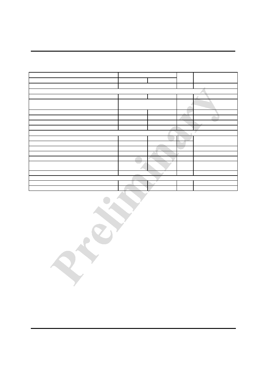
4-1 Optical interface specifications
Table 4.1
Optical interface specifications
Parts Number
1041x-V5-A-yy
Parameter
Symbol
Min Max
Units
Note
Bit rate
9.95328
Gbit/s
Transmitter
Optical output power
Po
-6
-1
dBm
Optical waveform
OC-192/STM-64
Unamplified Mask standard
Figure
4.1
G.693
Center wavelength
c
1290 1330
nm
Extinction ratio
Er
6.0
dB
Spectral maximum �20dB Width
20
1.0 nm
Side mode suppression ratio
SMSR
30
dB
Receiver
Minimum sensitivity
Pin
-14 dBm
BER@1x10
-12
Minimum overload
Pin
-1
dBm
Input wavelength
c_rx
1280 1580
nm
Rx Return loss
27
dB
Jitter performance
Jitter Generation
0.1 UIp-p
Bandpass
filter;
50k to 80MHz
Jitter Tolerance and Transfer
Compliant with GR-253
Figure 4.2,4.3
Optical path
Dispersion
D
Lrmax
40 ps/nm
Optical Path Penalty
1 dB
Condition; Case temperature: 0
to 70degC, NRZ,PRBS2
31
-1
, Mark ratio: 1/2,
Supply voltage:+3.3V,+1.8V,-5.2V each +/-5%

OC-192/STM-64 SERDES Transceiver module Specification; OAT1041x-V5-z-yy
Document NO: QPS-0302-020
Rev. DRAFT 0.5
OKI Electric Industry Co., Ltd Optical Components Company
OKI Electric Industry Co., Ltd Optical Components Company
OKI Electric Industry Co., Ltd Optical Components Company
OKI Electric Industry Co., Ltd Optical Components Company
5
OKI Confidential
0.2
0.75
0.25
0
-0.25
1
1.4
Logic 1
Logic 0
A
m
pl
i
t
ude
0
1
Time(UI)
Figure 4.1 Eye pattern mask
Input Jitter Amplitude [UIpp]
Jitter Frequency [Hz]
slope=-20dB/decade
15
1.5
0.15
10
2k
20k
400k
4M
slope=-20dB/decade
Acceptable Range
Figure 4.2 Jitter
Tolerance mask
Jitte
r Ga
in
[d
B]
0.1
120k
Frequency [Hz]
slope=-20dB/decade
Acceptable Range
Figure 4.3
Jitter Transfer mask
Comply GR693