 | –≠–ª–µ–∫—Ç—Ä–æ–Ω–Ω—ã–π –∫–æ–º–ø–æ–Ω–µ–Ω—Ç: B7AP-M1 | –°–∫–∞—á–∞—Ç—å:  PDF PDF  ZIP ZIP |
Document Outline
- First Page
- Ordering Information
- Specifications
- Engineering Data
- Operation
- Dimensions
- Precautions
- Contacting Omron
R
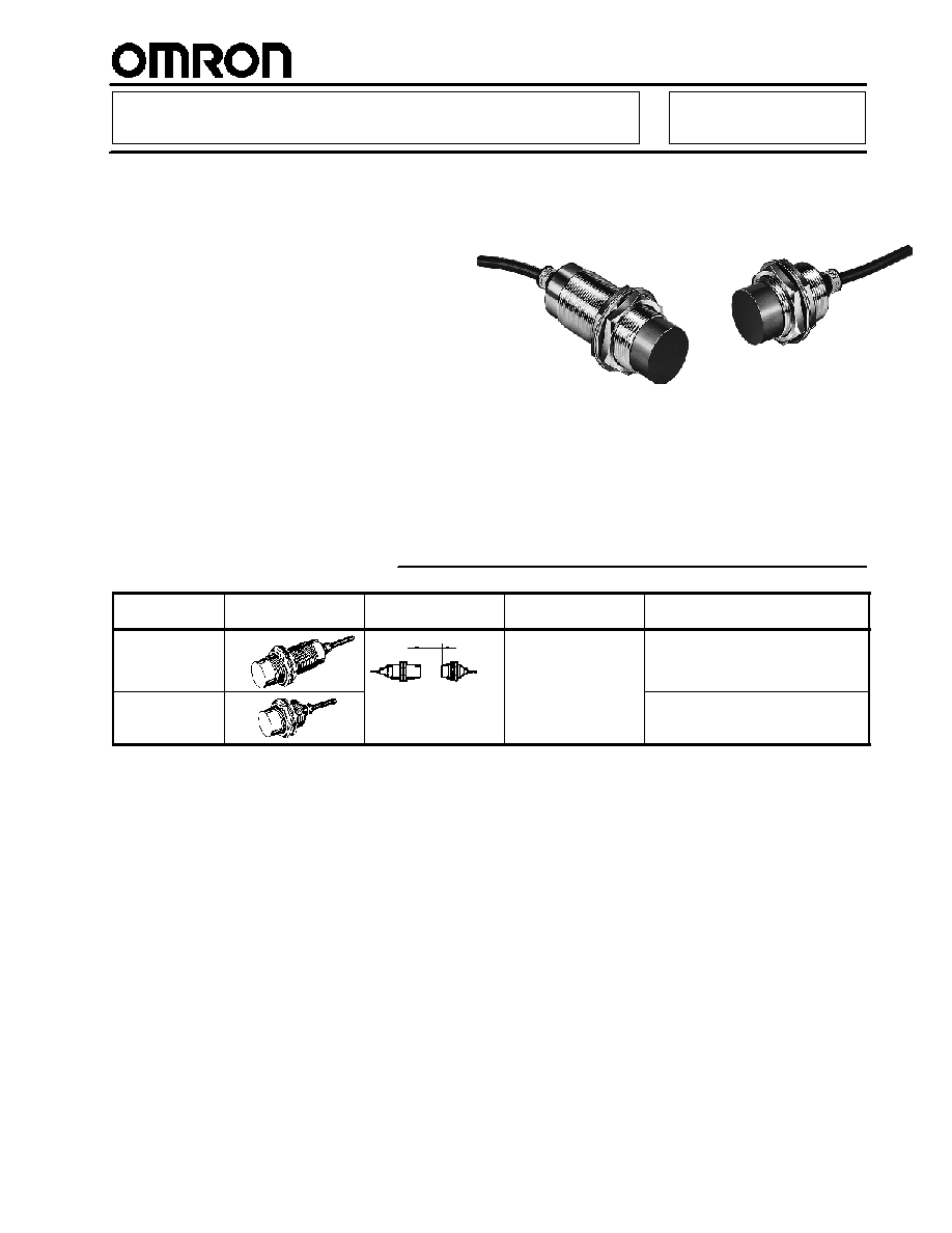
Inductive Power Couplers
B7AP
Allows Wireless Transmission of
ON/OFF Signals from Input Devices
and Power to Input Devices
H
Use the electromagnetic coupler to
transmit input signals to the B7A Output
Unit
H
Supplies power to the B7A Input Unit,
which means it does not require an
independent power supply
H
Wireless signal and power transmission
through a nonmetal object (such as
plastic or glass) is possible
Ordering Information
Classification
Appearance
Transmission distance
(couplers)
I/O delay
Part number
Stationary Unit
M30
8±1.5 mm
Typical: 19.2 ms
Max.:
31 ms
B7AP-S1 (See Note.)
Moving Unit
M30
(0.32 in ±0.06 in)
B7AP-M1
Note: The B7AP-S1 Power Coupler has a gauge that is used to adjust the transmission distance between the B7AP-S1 and B7AP-M1
Power Couplers.

B7AP
B7AP
2
J
B7A MODELS
Applicable B7A Link
Terminal
Max. I/O points
(See Note 1.)
Applicable input device
(See Note 3.)
Part number
B7A-R6B31
(See Note 2.)
---
B7AP-S1
B7A-R6C31
B7A-R6F31
B7A-R6G31
B7A-R6A52 (See Note 4.)
B7A-R6A33
B7A-R3A33
B7AS-R6B31
B7AM-6BS (See Note 4.)
B7A-T6j1
10 (16)
Two-wire sensor, contact
B7AP-M1
B7A-T6D2
10 (16)
Contact
B7A-T6E3
10 (16)
B7A-T3E3
10 (16)
B7AS-T6B1
10 (16)
Two-wire sensor, contact
B7AM-6BS
10 (16)
Note: 1. The maximum I/O points refers the maximum I/O points handled simultaneously by the B7A Input and Output Units. Figures in
parentheses indicate the maximum I/O points handled simultaneously by the B7A Input and Output Units each connected with
an independent power supply. Refer to Power Supplies in Operation Section of this data sheet.
2. The maximum I/O points are the same as the maximum input points of the B7A Input Unit connected to the B7AP-M1.
3. PLCs and three-wire sensors can be connected only if the B7A Input and Output Units are each connected with an independent
power supply. Refer to Power Supplies in Operation Section of this data sheet.
4. Set the error processing to the LOAD-OFF mode.
Specifications
J
COMMUNICATIONS SPECIFICATIONS
Communication method
Unidirectional, time-division multiplex
Transmission distance (couplers)
8±1.5 mm (0.32 in ± 0.06 in)
Transmission distance (B7A)
100 m max. (328 ft) See Note 1.
I/O delay
Typical: 19.2 ms; 31 ms max.
Minimum coupler interfacing time
0.3 s (See Note 2.)
Minimum distance between Power
Couplers mounted in parallel
60 mm (2.36 in)
Note: 1. The value is for the case where a power supply is provided only for the B7AP-S1.
2. Minimum coupler interfacing time is the minimum time required for signal and power transmission between the B7AP-S1 and
B7AP-M1 Power Couplers.

B7AP
B7AP
3
J
CHARACTERISTICS
Part number
B7AP-S1
B7AP-M1
Power supply voltage
24 VDC ±10%
---
Current consumption
300 mA
---
Insulation resistance
100 M min. (at 500 VDC) between each lead wire and external parts
Dielectric strength
1,000 VAC, 50/60 Hz for 1 min between each lead wire and external parts
Noise immunity
Noise level: 1.5 kV; pulse width: 100 ns to 1 µs (on transmission line due to coupling)
Vibration resistance
10 to 55 Hz, 1.5-mm double amplitude
Shock resistance
500 m/s
2
(1640.4 ft/sec
2
) approx. 50G
Ambient temperature
Operating
--10∞C to 55∞C (14∞F to 131∞F) with no icing or condensation
Ambient temperature
Storage
--25∞C to 65∞C (--13∞F to 149∞F) with no icing or condensation
Ambient humidity
Operating
35% to 95% (with no condensation)
Cable pulling strength
49 N (5 kgf) (11 lbs)
Nut tightening strength
39 N S m (400 kgf S cm) (28.7 ft S lbf)
Enclosure rating
IEC IP67
Maximum cable length
2 m (78.7 in)
Weight
Approx. 300 g (10.58 oz)
Approx. 230 g (8.11 oz)
EMC
Radiated Emissions:
EN55022 class A
Radiated Immunity:
prEN50082-2
Electrostatic Discharge:
prEN50082-2
Burst Transients:
prEN50082-2
Approved standards
UL508
Conforms to EN50081-2, EN50082-2
J
MOVING UNIT SPECIFICATIONS
Output voltage
12 VDC ±10%
Output current
38 mA
Note: Use the Moving Unit so that the total current consumption of all input devices is 38 mA max. if power is supplied to the input de-
vices through the Moving Unit.
Engineering Data
J
TRANSMISSION RANGE (REFERENCE)
Distance between Y axes (mm)
Availablezone
B: 2∞ max.
T
r
a
n
s
mi
s
s
i
o
n
d
i
s
t
a
n
c
e
X
(mm)

B7AP
B7AP
4
Operation
J
CONNECTION
B7A Output Unit
B7A Input Unit
B7AP-S1
B7AP-M1
24 VDC±10%
Brown
Black
Blue
Brown
Black
Blue
J
POWER SUPPLIES
Signal and Power Transmission (with Power Supplied to B7AP-S1)
Note: 1. The thickness of the extension cable for the B7AP-S1 Power Coupler must be 0.75 mm
2
min.
2. No extension cable can be connected to the B7AP-M1 Power Coupler. Use the original 2-m
cable connected to the B7AP-M1 Power Coupler.
3. Refer to page 2, B7A Models for the maximum input points of the B7A Input Unit.
4. No PLC or three-wire sensor can be connected to the B7A Input Unit.
Brown
Black
Blue
Brown
Black
Blue
B7A Output
Unit
B7A Input Unit
Extension cable
(96 m max.)
2 m
(standard)
Transmission
distance: 8±1.5 mm
(0.315 ±0.059)
Total length: 100 m max.
2 m
(standard)
24 VDC±10%
Signal Transmission Only (with Power Supplied to B7AP-S1 and B7AP-M1)
Note: 1. The thickness of the extension cable for the B7AP-S1 or B7AP-M1 Power Coupler must be 0.75 mm
2
min.
2. For transmitting signals only, the brown lead wire of the B7AP-M1 Power Coupler must not be used.
Insulate the brown lead wire with insulation tape so that the brown wire will not come in contact with
any lead wire.
3. The maximum input points of the B7A Input Unit are available.
4. PLCs and three-wire sensors can be connected to the B7A Input Unit.
Brown
Black
Blue
Brown
Black
Blue
B7A Output
Unit
24 VDC±10%
Transmission
distance: 8±1.5 mm
Total length: 500 m max.
Extension cable
(96 m max.)
2 m
(standard)
2 m
(standard)
Extension cable
(400m max.)
B7A Input
Unit
12 to 24 VDC
Open
(no connection)

B7AP
B7AP
5
J
INDICATORS
Indicators
Function
Power indicator
(B7AP-S1)
Lit
Lit when power is supplied to the Power Coupler.
Not lit
Not lit when power is not supplied to the Power Coupler.
Operation indicator
(B7AP-M1)
Lit
Lit when the B7AP-M1 and B7AP-S1 Power Couplers are properly set for wireless signal or
power transmission at a transmission distance of 8 ±1.5 mm. (0.32 ±0.06).
Not lit
Not lit when the B7AP-M1 and B7AP-S1 Power Couplers are not properly set for wireless
signal or power transmission, or the B7AP-M1 Power Coupler has excessive loads.
B7AP-S1
B7AP-M1
Power indicator
Operation indicator
Dimensions
Unit: mm (inch)
B7AP-M1
Mounting Holes
Mounting Holes
Toothed washer
Power indicator
Round vinyl-insulated cable
6 dia. (0.5 mm
2
)
Standard length: 2 m
Two, clamping nut
30.5
+0.5
0
dia.
Toothed
washer
Two, clamping nut
Operation indicator
Round vinyl-insulated cable
6 dia. (0.5 mm
2
)
Standard length: 2 m
30.5
+0.5
0
dia.
M30 x 1.5
M30 x 1.5
10
(0.39)
98 (3.86)
5
(0.20)
80 (3.15)
13
(0.51)
27.3 dia
(1.08)
85.3 (3.36)
36 (1.42)
42 dia (1.65)
36 (1.42)
42 dia (1.65)
13
(0.51)
43 (1.69)
5
(0.20)
48.3 (1.90)
61 (2.40)
27.3 dia
(1.08)
B7AP-S1
(1.2
+0.019
0
dia.)
(1.2
+0.019
0
dia.)

B7AP
B7AP
6
Precautions
J
GENERAL PRECAUTIONS
Be careful when touching the B7AP-S1 Power Coupler during
operation because the surface temperature of the B7AP-S1
Power Coupler will rise approximately 20∞C after the B7AP-S1
Power Coupler starts power transmission. The surface
temperature varies with the load of the sensing device connected
to the B7AP-M1 Power Coupler and the transmission distance.
J
HANDLING
Use the B7AP-S1 and B7AP-M1 Power Couplers with the
available B7A Link Terminals. Refer to page 2, B7A Models.
The M7E-12jj Display Unit, M7E-20jj Display Unit, and B7A
Link Terminals with an I/O delay of 3 ms cannot be used with the
B7AP-S1 or B7AP-M1 Power Coupler.
Use the LOAD-OFF model for the B7A Output Unit to be
connected to the B7AP-S1. When using a model that allows
selection of error processing, set to the LOAD-OFF mode. This
turns OFF signals right before an occurrence of a transmission
error and prevents unexpected signal transmission when the
transmission error is cleared.
Separate the Power Couplers 8±1.5 mm min. away from each
other. The distance between the Power Couplers on standby
must be 30 mm or more.
30 mm min.
Do not supply power to the B7AP-S1 or B7AP-M1 Power Coupler
while connecting the Power Couplers to the B7A Link Terminals.
Connect the Power Couplers to the B7A Link Terminals correctly,
otherwise the internal circuits of the Power Couplers may be
damaged.
The SIG terminal must not contact with the power supply
terminals, otherwise the internal elements may be damaged and
normal transmission may not be possible.
Brown(+)
Black(SIG)
Blue(-- )
Correct
Incorrect
Incorrect
Contact
Brown(+)
Black(SIG)
Blue(-- )
Black(SIG)
Brown(+)
Blue(-- )
Wire the cables of the B7AP-S1 and B7AP-M1 Power Couplers
through independent metal conduits to prevent the Power
Couplers from being influenced by noise if there are power or
high-tension lines nearby. Test the Power Couplers and make
sure that the Power Couplers operate normally before they are
put in actual operation.
Metal conduit
Power or high-tension line
Correct
Incorrect
Do not subject the head of the B7AP-S1 or B7AP-M1 Power
Coupler to excessive shock with hard objects.
Do not use the B7AP-S1 or B7AP-M1 Power Coupler outdoors
unless it is properly protected.
The B7AP-S1 and B7AP-M1 Power Couplers are products
meeting the requirements of IP67. The B7AP-S1 or B7AP-M1
Power Coupler cannot be, however, used in water or oil.
Keep the heads of the B7AP-S1 and B7AP-M1 Power Couplers
free from dust, otherwise improper signal or power transmission
may result between the Power Couplers.
J
MOUNTING
Use nuts and serrated toothed washers and tighten the nuts to
mount the B7AP-S1 and B7AP-M1 Power Couplers. The
tightening torque applied to each of the nuts must be 39 N S m
(28.7 ft S lbf) maximum. The mounting position will change and
improper signal or power transmission may result between the
Power Couplers if the nuts are not tightened properly.
39 NSm (28.7 ft S lbf) max.

B7AP
B7AP
7
J
TRANSMISSION DISTANCE FOR
STABLE SIGNAL AND POWER TRANS-
MISSION
The B7AP-S1 Power Coupler has a gauge that is used to adjust
the transmission distance between the B7AP-S1 and B7AP-M1
Power Couplers. Use the gauge to adjust the transmission
distance to 8 mm, make sure that the green operation indicator of
the B7AP-M1 Power Coupler is lit, and the B7A Output Unit has
no error output before operating the Power Couplers.
Gauge
Operation
indicator
8 mm
J
MONITORING TRANSMISSION STATUS
Judge from the power supply/error indicator and error output of
the B7A Output Unit whether the B7AP-S1 and B7AP-M1 Power
Couplers are facing each other correctly.
The error output of the B7A Output Unit will be ON when the
B7AP-S1 and B7AP-M1 Power Couplers are not facing each
other correctly.
J
MINIMUM DISTANCE BETWEEN POWER
COUPLERS MOUNTED IN PARALLEL
When mounting the B7AP-S1 and B7AP-M1 Power Couplers in
parallel, refer to the following table. Keep at least the specified
minimum distance between adjacent Power Couplers for proper
heat radiation by considering the temperature rise (approximately
20∞C) of the B7AP-S1 Power Couplers in operation.
Item
B7AP-S1
B7AP-M1
60 mm (2.36 in)
60 mm (2.36 in)
J
EFFECTS OF SURROUNDING METAL
The B7AP Power Coupler may malfunction when affected by
surrounding metal. When mounting the B7AP within a metal
panel, ensure that the clearances given in the following table are
maintained. Be sure to check in advance that the B7AP operates
correctly.
d dia.
Item
B7AP-S1
B7AP-M1
20 mm (0.79 in)
20 mm (0.79 in)
d
60 mm dia. (2.36 in) 60 mm dia. (2.36 in)
D
20 mm (0.79 in)
20 mm (0.79 in)
n
60 mm (2.36 in)
60 mm (2.36 in)
J
MAINTENANCE
Regularly check these items for the stable operation of the
B7AP-S1 and B7AP-M1 Power Couplers:
∑
The mounting positions and the tightening of the mounting
nuts.
∑
The tightening, contacts, and breaking of the lead wires.
∑
Dust accumulation on the heads.
∑
The ambient operating temperature and other operating
conditions.
∑
The transmission distance.

B7AP
B7AP
Cat. No. CEDSAX4 11/01 Specifications subject to change without notice. Printed in U.S.A .
OMRON ELECTRONICS LLC
One East Commerce Drive
Schaumburg, IL 60173
NOTE: DIMENSIONS SHOWN ARE IN MILLIMETERS. To convert millimeters to inches divide by 25.4.
1-800-55-OMRON
OMRON CANADA, INC.
885 Milner Avenue
Scarborough, Ontario M1B 5V8
416-286-6465
R
OMRON ON--LINE
Global -- http://www.omron.com
USA -- http://www.omron.com/oei
Canada -- http://www.omron.com/oci