Solid State Relay
G3M
1
Solid State Relay
G3M
1, 2, 3 and 5 A single in-line package SSR
D
Thin design for high-density PCB applications.
D
DC input-AC output for up to a 5-A load.
D
Two foot prints offer greater flexibility.
D
Approved by UL and CSA.
Ordering Information
To order: Select the part number and add the desired coil voltage rating, (e.g., G3M-202P-US DC5)
Isolation
Input terminal
pitch
Zero cross
function
Indicator
Rated output load
(Applicable output load)
Rated input voltage
Model
Phototriac
7.62 mm
Yes
No
2 A at 100 to 240 VAC
(2 A t 75 t 264 VAC)
5 VDC
G3M-202P-US
(2 A at 75 to 264 VAC)
12 VDC
24 VDC
3 A at 100 to 240 VAC
(3 A t 75 t 264 VAC)
5 VDC
G3M-203P
(3 A at 75 to 264 VAC)
12 VDC
24 VDC
No
2 A at 100 to 120 VAC
(2 A t 75 t 132 VAC)
5 VDC
G3M-102PL-US
(2 A at 75 to 132 VAC)
12 VDC
24 VDC
2 A at 100 to 240 VAC
(2 A t 75 t 264 VAC)
5 VDC
G3M-202PL-US
(2 A at 75 to 264 VAC)
12 VDC
24 VDC
3 A at 100 to 240 VAC
(3 A t 75 t 264 VAC)
5 VDC
G3M-203PL
(3 A at 75 to 264 VAC)
12 VDC
24 VDC
5 A at 100 to 240 VAC
(5 A t 75 t 264 VAC)
5 VDC
G3M-205PL
(5 A at 75 to 264 VAC)
12 VDC
24 VDC
(This table continues on the next page.)

3
Solid State Relay
G3M
J
CHARACTERISTICS
Item
G3M-102PL-US (-4)
G3M-202P(L)-US (-4)
G3M-203P(L) (-4)
G3M-205P(L) (-4)
Operate time
1 ms max. (1/2 of load power source cycle + 1 ms max. for G3M-202P, G3M-203P, G3M-205P)
Release time
1/2 of load power source cycle + 1 ms max.
Output ON voltage drop
1.6 V (RMS) max.
Leakage current
2 mA max. (at 100 VAC)
2 mA max. (at 100 VAC)
5 mA max. (at 200 VAC)
1.5 mA (at 200 VAC)
Insulation resistance
1,000 M min. (at 500 VDC)
Dielectric strength
2,000 VAC, 50/60 Hz for 1 min
2,500 VAC, 50/60 Hz for 1 min
Vibration resistance
Malfunction: 10 to 55 Hz, 1.5-mm double amplitude
Shock resistance
Malfunction: 1,000 m/s
2
{approx. 100G}
Ambient temperature
Operating: --30�C to 80�C (with no icing or condensation)
Storage:
--30�C to 100�C (with no icing or condensation)
Approved standards
UL508 File No.E64562/CSA C22.2 (No.0, No.14) File No. LR35535
T�V R9551055 (EN60950)
Ambient humidity
Operating: 45% to 85%
Weight
Approx. 15 g
Approx. 25 g
J
APPROVALS
UL (File No. E64562)/CSA (File No. LR35535)
Input Voltage
SSR Type
Load Rating
5, 12, 24 VDC
With Suffixes 102 and
US or UTU
2 A, 125 VAC, Resistive 250 W, 125 VAC, Tungsten 2 A FLA, 12 A LRA, 125 VAC
With Suffixes 202 and
US
2 A, 250 VAC, Resistive 500 W, 250 VAC, Tungsten 2 A FLA, 12 A LRA, 250 VAC
With Suffixes 202
UTU, UTU-1, and
UTU-2
2 A, 250 VAC, Resistive 250 W, 250 VAC, Tungsten 1 FLA, 6 LRA, 250 VAC
With Suffixes 103 and
US or UTU
3 A, 125 VAC, Resistive 375 W, 125 VAC, Tungsten 1.5 A FLA, 9 A LRA, 125 VAC
With Suffixes 203 and
US or UTU
3 A, 250 VAC, Resistive 750 W, 250 VAC, Tungsten 1.5 A FLA, 9 A LRA, 250 VAC
With Suffix 105
5 A, 125 VAC, Resistive 625 W, 125 VAC, Tungsten 2.5 A FLA, 15 A LRA, 125 VAC
With Suffix 205
5 A, 250 VAC, Resistive 1250 W, 250 VAC, Tungsten 2.5 A FLA, 15 A LRA, 250 VAC
4
Solid State Relay
G3M
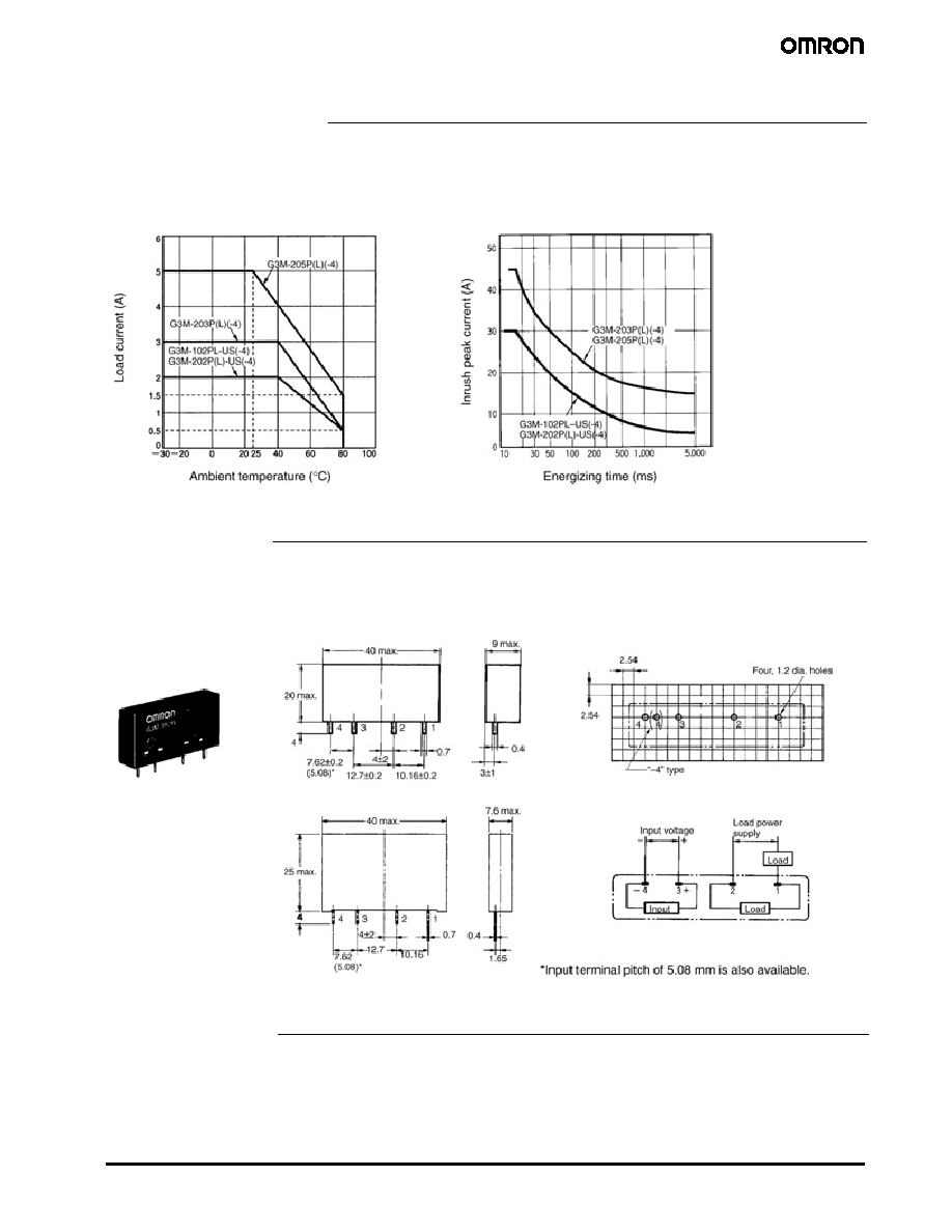
Engineering Data
Load Current vs. Temperature Ambient
Inrush Current Immunity
Non-repetitive
Reduce the current to 1/2 or less if the
G3M is in repetitive operation.
Dimensions
Note: All units are in millimeters unless otherwise indicated.
PCB Dimensions
(Bottom View)
G3M-102PL-US(-4), G3M-202P(L)-US(-4)
G3M-203P(L)(-4)
G3M-205P(L)(-4)
Terminal Arrangement
(Bottom View)
Precautions
Protective Element
No overvoltage absorption element is built in. Therefore, if the G3M
is connected to an inductive load, be sure to connect the overvol-
tage absorption element.

5
Solid-State Relay
G
3M
OMRON ON-LINE
Global - http://www.omron.com
USA - http://www.omron.com/oei
Canada - http://www.omron.ca
ALL DIMENSIONS SHOWN ARE IN MILLIMETERS. To convert millimeters into inches, divide by 25.4
Cat. No. GC RLY8
5/03 Specifications subject to change without notice Printed in USA
OMRON CANADA, INC.
885 Milner Avenue
Toronto, Ontario M1B 5V8
416-286-6465
OMRON ELECTRONICS LLC
One Commerce Drive
Schaumburg, IL 60173
847-882-2288