©
Semiconductor Components Industries, LLC, 2002
March, 2002 ≠ Rev. 2
1
Publication Order Number:
NTHD5905T1/D
NTHD5905T1
Power MOSFET
Dual P-Channel ChipFETt
3.0 Amps, 8 Volts
Features
∑
Low R
DS(on)
for Higher Efficiency
∑
Logic Level Gate Drive
∑
Miniature ChipFET Surface Mount Package
Applications
∑
Power Management in Portable and Battery≠Powered Products; i.e.,
Cellular and Cordless Telephones and PCMCIA Cards
MAXIMUM RATINGS
(T
A
= 25
∞
C unless otherwise noted)
Rating
Symbol
5 secs
Steady
State
Unit
Drain≠Source Voltage
V
DS
≠8.0
V
Gate≠Source Voltage
V
GS
"
8.0
V
Continuous Drain Current
(T
J
= 150
∞
C) (Note 1)
T
A
= 25
∞
C
T
A
= 85
∞
C
I
D
"
4.1
"
2.9
"
3.0
"
2.2
A
Pulsed Drain Current
I
DM
"
10
A
Continuous Source Current
(Diode Conduction) (Note 1)
I
S
≠1.8
≠0.9
A
Maximum Power Dissipation
(Note 1)
T
A
= 25
∞
C
T
A
= 85
∞
C
P
D
2.1
1.1
1.1
0.6
W
Operating Junction and Storage
Temperature Range
T
J
, T
stg
≠55 to +150
∞
C
1. Surface Mounted on 1
x 1
FR4 Board.
G
S
D
P≠Channel MOSFET
1
1
1
G
S
D
2
2
2
P≠Channel MOSFET
D
2
2
S
G
2
D1
1
G
1
S
D2
D1
1
2
3
4
5
6
7
8
Device
Package
Shipping
ORDERING INFORMATION
NTHD5905T1
ChipFET
3000/Tape & Reel
PIN CONNECTIONS
ChipFET
CASE 1206A
STYLE 2
MARKING
DIAGRAM
A9
A9 = Specific Device Code
1
2
3
4
8
7
6
5
DUAL P≠CHANNEL
3.0 AMPS, 8 VOLTS
R
DS(on)
= 90 m
W
http://onsemi.com
NTHD5905T1
http://onsemi.com
2
THERMAL CHARACTERISTICS
Characteristic
Symbol
Typ
Max
Unit
Maximum Junction≠to≠Ambient (Note 2)
t
v
5 sec
Steady State
R
thJA
50
90
60
110
∞
C/W
Maximum Junction≠to≠Foot (Drain)
Steady State
R
thJF
30
40
∞
C/W
ELECTRICAL CHARACTERISTICS
(T
J
= 25
∞
C unless otherwise noted)
Characteristic
Symbol
Test Condition
Min
Typ
Max
Unit
Static
Gate Threshold Voltage
V
GS(th)
V
DS
= V
GS
, I
D
= ≠250
m
A
≠0.45
≠
≠
V
Gate≠Body Leakage
I
GSS
V
DS
= 0 V, V
GS
=
"
8.0 V
≠
≠
"
100
nA
Zero Gate Voltage Drain Current
I
DSS
V
DS
= ≠6.4 V, V
GS
= 0 V
≠
≠
≠1.0
m
A
V
DS
= ≠6.4 V, V
GS
= 0 V,
T
J
= 85
∞
C
≠
≠
≠5.0
On≠State Drain Current (Note 3)
I
D(on)
V
DS
v
≠5.0 V, V
GS
= ≠4.5 V
≠10
≠
≠
A
Drain≠Source On≠State Resistance (Note 3)
r
DS(on)
V
GS
= ≠4.5 V, I
D
= ≠3.0 A
≠
0.075
0.090
W
(
)
V
GS
= ≠2.5 V, I
D
= ≠2.5 A
≠
0.110
0.130
V
GS
= ≠1.8 V, I
D
= ≠1.0 A
≠
0.150
0.180
Forward Transconductance (Note 3)
g
fs
V
DS
= ≠5.0 V, I
D
= ≠3.0 A
≠
7.0
≠
S
Diode Forward Voltage (Note 3)
V
SD
I
S
= ≠0.9 A, V
GS
= 0 V
≠
≠0.8
≠1.2
V
Dynamic (Note 4)
Total Gate Charge
Q
g
V
4 0 V V
4 5 V
≠
5.5
9.0
nC
Gate≠Source Charge
Q
gs
V
DS
= ≠4.0 V, V
GS
= ≠4.5 V,
I
D
= ≠3.0 A
≠
0.5
≠
Gate≠Drain Charge
Q
gd
I
D
= ≠3.0 A
≠
1.5
≠
Turn≠On Delay Time
t
d(on)
≠
10
15
ns
Rise Time
t
r
V
DD
= ≠4.0 V, R
L
= 4
W
I
D
^
≠1 0 A V
GEN
= ≠4 5 V
≠
45
70
Turn≠Off Delay Time
t
d(off)
I
D
^
≠1.0 A, V
GEN
= ≠4.5 V,
R
G
= 6
W
≠
30
45
Fall Time
t
f
R
G
6
W
≠
10
15
Source≠Drain Reverse Recovery Time
t
rr
I
F
= ≠0.9 A, di/dt = 100 A/
m
s
≠
30
60
2. Surface Mounted on 1
x 1
FR4 Board.
3. Pulse Test: Pulse Width
v
300
m
s, Duty Cycle
v
2%.
4. Guaranteed by design, not subject to production testing.
NTHD5905T1
http://onsemi.com
3
TYPICAL ELECTRICAL CHARACTERISTICS
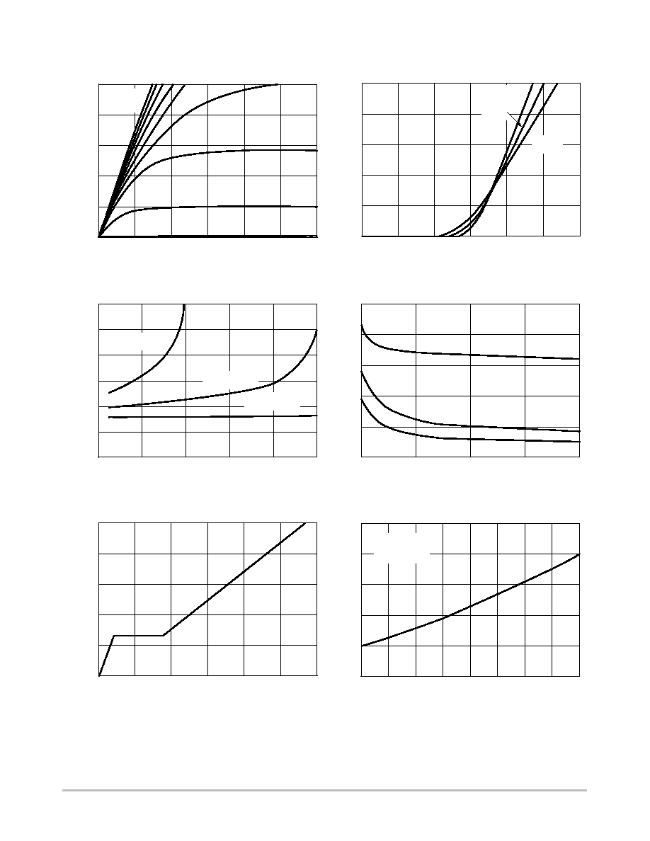
Figure 1. Output Characteristics
10
8
6
4
2
0
0
0.5
1.0
1.5
2.0
2.5
3.0
2.5 V
2 V
1.5 V
1 V
C
oss
10
8
6
4
2
0
0
0.5
1.0
1.5
2.0
2.5
T
C
= ≠55
∞
C
25
∞
C
125
∞
C
V
GS
= 4.5 V
V
GS
= 1.8 V
5
4
3
2
1
0
0
2
3
4
0.30
0.25
0.15
0.05
0
0
2
4
6
8
10
1000
400
200
0
0
4
8
12
16
20
C
iss
C
rss
1.6
1.4
1.2
1.0
0.8
0.6
≠50
≠25
0
25
50
75
100
125
150
V
GS
= 4.5 V
I
D
= 3 A
1
3.0
0.20
0.10
800
600
V
GS
= 2.5 V
4
5
6
≠V
DS
, Drain≠to≠Source Voltage (V)
≠V
GS
, Gate≠to≠Source Voltage (V)
≠I
D,
Drain Current (A)
≠I
D
, Drain Current (A)
≠V
DS
, Drain≠to≠Source Voltage (V)
C, Capacitance (pF)
r DS(on),
On≠Resistance (
)
Q
g,
Total Gate Charge (nC)
V
GS,
Gate≠to≠Source V
oltage (V)
(Normalized)
T
J
, Junction Temperature (
∞
C)
r DS(on),
On≠Resistance (
)
Figure 2. Transfer Characteristics
Figure 3. On≠Resistance vs. Drain Current
Figure 4. Capacitance
Figure 5. Gate Charge
Figure 6. On≠Resistance vs.
Junction Temperature
V
GS
= 5
thru 3 V
≠I
D,
Drain Current (A)

NTHD5905T1
http://onsemi.com
4
TYPICAL ELECTRICAL CHARACTERISTICS
≠V
DS
, Drain≠to≠Source Voltage (V)
I S,
Source Current (A)
≠V
GS
, Gate≠to≠Source Voltage (V)
r DS(on),
On≠Resistance (
)
T
J
, Temperature (
∞
C)
V
GS (th),
V
arience (V)
1
10
0
0.2
0.4
0.6
0.8
1.0
1.2
T
J
= 150
∞
C
T
J
= 25
∞
C
0.20
0.15
0.10
0.05
0
0
1
2
3
4
5
I
D
= 3 A
0.3
≠50
≠25
0
25
50
75
100
125
150
I
D
= 250
m
A
Power (W)
50
40
30
20
10
10
10≠3
≠2
≠1
10
1
10
100
600
Time (sec)
0.4
0
10≠4
1.4
0.25
0.2
0.1
0.0
≠0.1
≠0.2
Figure 7. Source Diode Forward Voltage
Figure 8. On≠Resistance vs. Gate≠to≠Source
Voltage
Figure 9. Threshold Voltage
Figure 10. Single Pulse Power
NTHD5905T1
http://onsemi.com
5
TYPICAL ELECTRICAL CHARACTERISTICS
2
1
0.1
0.01
10
10
10
≠4
≠3
≠2
≠1
10
1
10
0.02
Square Wave Pulse Duration (sec)
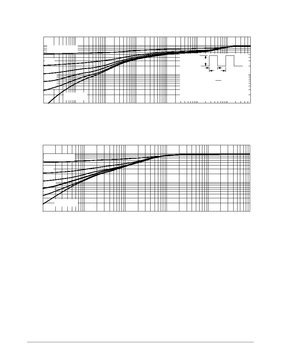
Duty Cycle = 0.5
0.2
Single Pulse
0.1
0.05
Normalized Ef
fective
T
ransient
Thermal Impedance
2
1
0.1
0.01
10
10
10
≠4
≠3
≠2
≠1
10
1
10
100
600
Square Wave Pulse Duration (sec)
Normalized Ef
fective
T
ransient
Thermal Impedance
Duty Cycle = 0.5
0.2
Single Pulse
0.1
0.05
0.02
1. Duty Cycle, D =
2. Per Unit Base = R
thJA
= 90
∞
C/W
3. T
JM ≠
T
A
= P
DM
Z
thJA
(t)
4. Surface Mounted
t 1
t 2
PDM
Notes:
t 1
t 2
Figure 11. Normalized Thermal Transient Impedance, Junction≠to≠Ambient
Figure 12. Normalized Thermal Transient Impedance, Junction≠to≠Foot