OPTEK reserves the right to make changes at any time in order to improve design and to supply the best product possible.
Optical Emitter and Sensor Pair
OPB100Z, OPB100EZ, OPB100SZ
OPTEK Technology Inc. -- 1645 Wallace Drive, Carrollton, Texas 75006
Phone: (972) 323-2200 or (800) 341-4747
FAX: (972) 323-2396 sensors@optekinc.com www.optekinc.com
Issue A.1 01/06
Page 1 of 3
Features:
∑
890 nm infrared LED emitter
∑
Silicon phototransistor sensor
∑
Snap-in mounting
∑
Variable sensing distance over 36" (91.4 cm)
∑
Low profile package
∑
24" (61.0 cm) wire leads
Description:
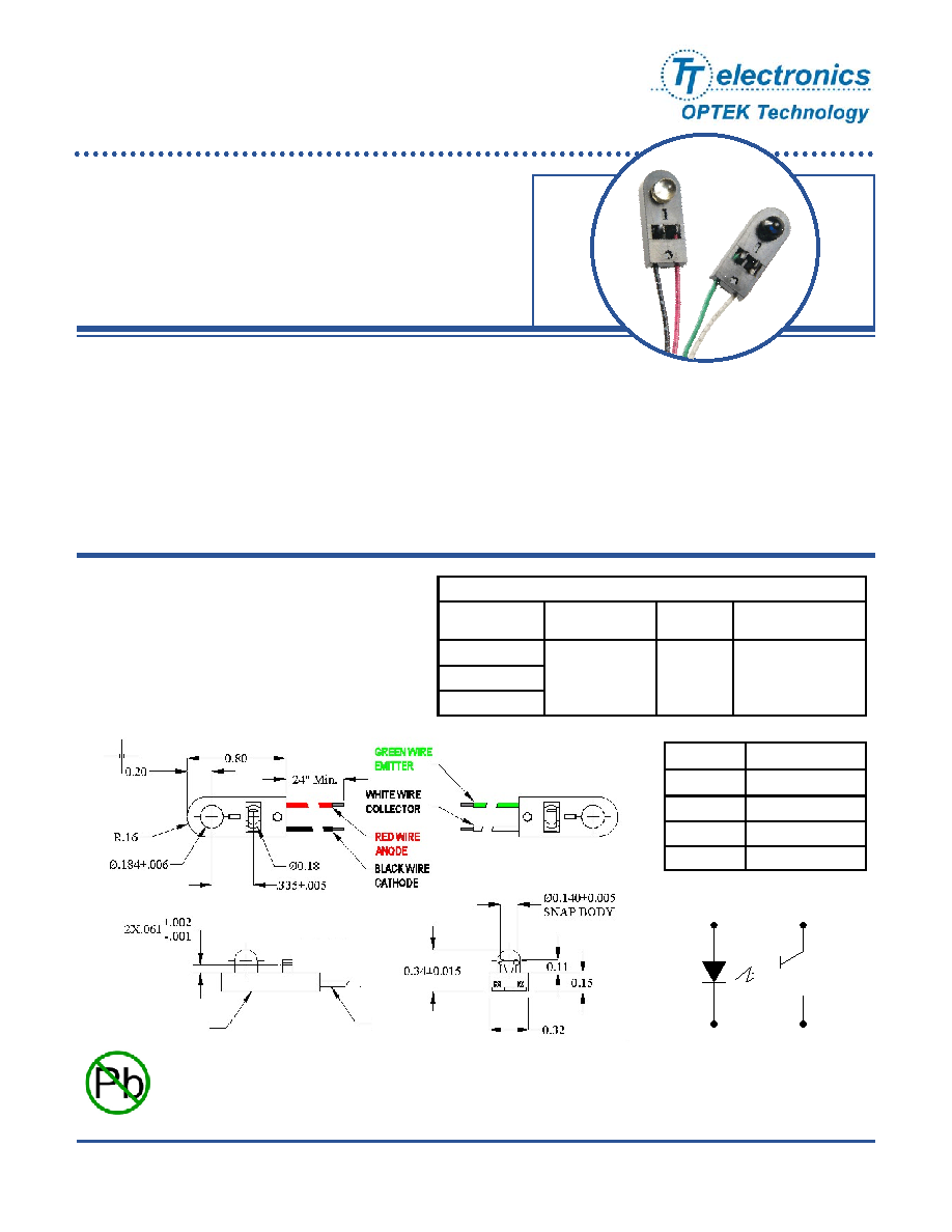
The OPB100 series consists of an infrared LED (OPB100EZ) and phototransistor (OPB100SZ) in separate
plastic housings. The low cost, snap-in design requires no screws or other mounting hardware for ease of
installation.
The emitter and sensor are not apertured, which allows separation distances in excess of 36" (91.4 cm) without
concern for precise alignment. The front side clip allows mounting of the product to any 0.062" (1.57 mm) thick
material.
This product is designed for general switching and low-speed data communications applications.
Red
Black
White
Green
Ordering Information
Part
Number
LED Peak
Wavelength
Sensor
Lead Length /
Spacing
OPB100Z
880 nm
Transistor
OPB100-EZ
OPB100-SZ
24" / 26 AWG Wire
Applications:
∑
Non-contact reflective object
∑
Non-contact interruptive sensing
∑
Assembly line automation
∑
Machine automation
∑
Machine safety
SNAP BODY
Emitter (LED)
Phototransistor
Symbolize Cover
26 AWG
UL Rated
Color/Pin Description
Red-1 Anode
Black-2 Cathode
White-3 Collector
Green-4 Emitter
RoHS

OPTEK reserves the right to make changes at any time in order to improve design and to supply the best product possible.
Optical Emitter and Sensor Pair
OPB100Z, OPB100EZ, OPB100SZ
OPTEK Technology Inc. -- 1645 Wallace Drive, Carrollton, Texas 75006
Phone: (972) 323-2200 or (800) 341-4747
FAX: (972) 323-2396 sensors@optekinc.com www.optekinc.com
Issue A .1 01/06
Page 2 of 3
Electrical Characteristics
(T
A
= 25
∞
C unless otherwise noted -- for reference only)
SYMBOL PARAMETER MIN
TYP
MAX
UNITS TEST
CONDITIONS
Input Diode (See OP298 for additional information -- for reference only)
V
F
Forward
Voltage
- - 1.7 V I
F
= 20 mA
I
R
Reverse
Current
- - 15 µA
V
R
= 10 V
q
HP
Emission Angle at Half Power Points
-
25
-
Degree I
F
= 20 mA
E
E
(APT) Aperture Radiant Incidence
2.4
-
-
mW/cm
2
I
F
= 100 mA
Distance = 1.43" (3.63 cm)
Aperture = 0.25" (6.35 mm)
Output Phototransistor (See OP598 for additional information -- for reference only)
V
(BR)CEO
Collector-Emitter
Breakdown
Voltage 30 -
-
V I
C
= 1 mA, E
E
= 0mw/cm
2
(no light)
V
(BR)ECO
Emitter-Collector
Breakdown
Voltage 5 -
-
V I
C
= 100 µA, E
E
= 0mw/cm
2
(no light)
I
CEO
Collector
Dark
Current
- - 100 nA
V
CE
= 10V, I
F
= 0, E
E
= 0 mw/cm
2
(no light)
V
CE(SAT)
Collector-Emitter
Saturation Voltage
-
-
0.4
V
I
C
= 400 µA, E
E
= 1.7 mw/cm
2
I
C(ON)
On-State Collector Current
5
-
-
mA
V
CE
= 5 V, E
E
= 1.7 mw/cm
2
Notes:
1.
Derate linearly 3.33mW/
∞
C above 25
∞
C.
2.
All parameters measured using pulse technique.
3.
Derate linearly 1.43mW/∞C above 25∞C.
Absolute Maximum Ratings
(T
A
=25∞C unless otherwise noted)
Storage Temperature Range
-40
o
C to +85
o
C
Operating Temperature Range
(1)
-40
o
C to +80
o
C
Input LED (OP298 for additional information)
Forward DC Current
100 mA
Peak Forward Current (1 µs pulse width, 300 pps)
1 A
Reverse DC Voltage
2 V
Power Dissipation
(2)
142 mW
Collector-Emitter Voltage
30 V
Emitter-Collector Voltage
5 V
Output Phototransistor (OP598 for additional information)
Collector DC Current
50 mA
Power Dissipation
(3)
250 mW

OPTEK reserves the right to make changes at any time in order to improve design and to supply the best product possible.
Optical Emitter and Sensor Pair
OPB100Z, OPB100EZ, OPB100SZ
OPTEK Technology Inc. -- 1645 Wallace Drive, Carrollton, Texas 75006
Phone: (972) 323-2200 or (800) 341-4747
FAX: (972) 323-2396 sensors@optekinc.com www.optekinc.com
Issue A.1 01/06
Page 3 of 3
Output Current vs. Distance
0.01
0.1
1
10
100
1
2
3
4
5
6
7
8
9
10
11
12
Distance (inches)
Ty
p
i
c
a
l
O
u
t
put
C
u
r
r
e
n
t
(
m
A
)
IF=20 mA
IF=50 mA