
OPTEK reserves the right to make changes at any time in order to improve design and to supply the best product possible.
OPTEK Technology Inc. -- 1645 Wallace Drive, Carrollton, Texas 75006
Phone: (972) 323-2200 or (800) 341-4747
FAX: (972) 323-2396 sensors@optekinc.com www.optekinc.com
Issue A.4 02/06
Page 1 of 4
Tube Liquid Sensor
OPB350 Series
Applications:
∑
Non-contact fluid sensing
∑
IV fluid
∑
Oils and other petroleum products
∑
Colored fluids
∑
Toner fluids
∑
Water
Ordering Information
Part Number
Package
LED Peak
Wavelength
Sensor
Tube
Size
Lead Length /
Spacing
OPB350
N
890 nm
Transistor
0.125"
0.330" / 0.320"
OPB350L187
0.187"
OPB350L250
0.250"
OPB350W187Z
0.187"
24" / 26 AWG Wire
OPB350W250Z
0.250"
T
Features:
∑
Can identify if liquid is present in clear tubes that have an
outside diameter of 1/8" (3.2mm), 3/16" (4.8mm) or 1/4" (6.3mm)
∑
Opaque plastic housing enhances ambient light rejection
∑
Printed circuit board mounting or 24" (610 mm) wires
Description:
The OPB350 series liquid sensor is designed to work with 1/8" (3.2mm), 3/16" (4.8mm) and 1/4" (6.3mm) outside
diameter clear tubes. When output reference circuitry is added, multiple output states such as "fluid present," "no
fluid present" and "no tube present" can be recognized.
Clear liquid present causes the phototransistor to sink the maximum current, while dark liquid present causes it to
sink the minimum current. As bubbles pass through the tube, the signal will vary between the "liquid present" and
"no liquid" states. If no liquid is present, the phototransistor sinks only a small amount of current. If no tube is
present, the phototransistor sinks a larger current than in the "no liquid" state.
Smaller outside diameter tubes can be used when the tube is sized up to one of the standard sizes and is fitted
properly in the housing opening. For example, fluid in a 1/16" (1.6mm) outside diameter tube can be sensed
when a piece of tubing with a 1/8" (3.2mm) outside diameter and a 1/16" (1.6mm) inside diameter is used as an
adapter.
Product Photo Here
Opto Switch
C1=
0
.1 uf
R4=2K
R1=
1
K
LM393
or
LM339
LM393
or
LM339
R2=
2
K
R3=
7
50
Vcc
Gnd
Vcc
Vth
Vth
Vth
Gnd
Vth
R1=
5
0
0
R4=2.5K
C1=
0
.1 uf
1
1
2
2
Output
Output
1
2
Typical Application Circuit
4
OPB350
"N"
Package
"T"
Package
RoHS
OPTEK Technology Inc. -- 1645 Wallace Drive, Carrollton, Texas 75006
Phone: (972) 323-2200 or (800) 341-4747
FAX: (972) 323-2396 sensors@optekinc.com www.optekinc.com
Issue A.4 02/06
Page 2 of 4
Tube Liquid Sensor
OPB350 Series
OPTEK reserves the right to make changes at any time in order to improve design and to supply the best product possible.
1
2
3
4
1
2
3
4
Pin #
LED
Pin #
Transistor
Red Anode White
Collector
Black Cathode Green Emitter
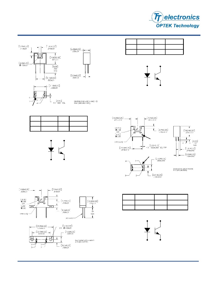
OPB350W187Z and OPB350W250Z
OPB350L187 and OPB350L250
OPB350
Pin #
LED
Pin # Transistor
1 Anode 3 Collector
2 Cathode 4 Emitter
Red-1
Black-2
White-3
Green-4
Pin #
LED
Pin # Transistor
1 Anode 3 Collector
2 Cathode 4 Emitter
Dot
Dot
Dot

OPTEK reserves the right to make changes at any time in order to improve design and to supply the best product possible.
OPTEK Technology Inc. -- 1645 Wallace Drive, Carrollton, Texas 75006
Phone: (972) 323-2200 or (800) 341-4747
FAX: (972) 323-2396 sensors@optekinc.com www.optekinc.com
Issue A.4 02/06
Page 3 of 4
Tube Liquid Sensor
OPB350 Series
Notes:
(1) All parameters tested using pulse technique.
(2) RMA flux is recommended. Duration can be extended to 10 seconds maximum when flow soldering.
(3) Methanol or isopropanol are recommended as cleaning agents. The plastic housing is soluble in chlorinated hydrocarbons and
keytones.
(4) Derate linearly 1.33 mW/∞ C above 25∞ C.
(5) E
e(APT)
is a measurement of the average apertured radiant energy incident upon a sensing area 0.250" (6.350 mm) in diameter,
which is perpendicular to and centered to the mechanical axis of the emitting surface at a distance of 0.466" (11.837 mm).
E
e(APT)
is not necessarily uniform within the measured area.
Absolute Maximum Ratings
(T
A
=25∞C unless otherwise noted)
Storage Temperature
-40∞ C to +100∞ C
Operating Temperature
-40∞ C to +85∞ C
Lead Soldering Temperature [1/16 inch (1.6mm) from the case for 5 sec. with soldering iron]
(2)
260∞
C
LED
Forward DC Current
50 mA
Peak Forward Current (2 µs pulse width, 0.1% duty cycle)
1 A
Reverse DC Voltage
2 V
Power Dissipation
100 mW
Output Phototransistor
Collector-Emitter Voltage
25 or 30 V
Collector DC Current
50 mA
Power Dissipation
100 mW
Electrical Characteristics
(T
A
= 25
∞
C unless otherwise noted)
SYMBOL PARAMETER MIN
TYP
MAX
UNITS
TEST
CONDITIONS
Input LED (See OPB245 for additional information -- for reference only)
V
F
Forward
Voltage
- - 1.8 V I
F
= 20 mA
I
R
Reverse Current
-
-
100
µA V
R
= 2.0 V
Output Phototransistor (See OPB555 [PB350] & OP750 [-187 & -250] for additional information -- for reference only)
V
(BR)CEO
Collector-Emitter
OPB350
Breakdown Voltage
-187 & -250
30
25
-
-
-
-
V I
C
= 100 µA, E
E
= 0 mw/cm
2
I
CEO
Collector-Emitter
Dark
Current
- - 100 nA V
CE
= 10 V, I
F
= 0, E
E
= 0 mw/cm
2
Coupled (Tested using clear 0.125" O.D., 0.062 I.D. nylon tubing)
V
CE(SAT)
Collector-Emitter
Saturation Voltage
-
-
0.4
V
I
C
= 100 µA, I
F
= 5 mA
I
C(ON)
On-State Collector Current
OPB350
OPB350L187 & OPB350W187
OPB350L250 & OPB350W250
1
1
0.75
3.5
2
1.5
6
4
3
mA
mA
mA
V
CE
= 0.4 V, I
F
= 5 mA
V
CE
= 0.4 V, I
F
= 5 mA
V
CE
= 0.4 V, I
F
= 5 mA
On/Off
Ratio
OPB350
OPB350L187 & OPB350W187
OPB350L250 & OPB350W250
-
-
-
3
2.3
2.3
-
-
-
-
-
-
V
CE
= 0.4 V, I
F
= 5 mA , I.D.=0.0625"
V
CE
= 0.4 V, I
F
= 5 mA , I.D.=0.0870"
V
CE
= 0.4 V, I
F
= 5 mA , I.D.=0.1250"

OPTEK Technology Inc. -- 1645 Wallace Drive, Carrollton, Texas 75006
Phone: (972) 323-2200 or (800) 341-4747
FAX: (972) 323-2396 sensors@optekinc.com www.optekinc.com
Issue A.4 02/06
Page 4 of 4
Tube Liquid Sensor
OPB350 Series
OPTEK reserves the right to make changes at any time in order to improve design and to supply the best product possible.
(
)
0.0
0.2
0.4
0.6
0.8
1.0
1.2
-40
-20
0
20
40
60
80
100
Rel
a
t
i
v
e
I
C(
ON
)
Normalized @ T=20∞C
Normalized I
C(ON)
vs Temperature
Temperature (∞C)
0.00
0.01
0.02
0.03
0.04
0.05
0.06
0.07
0.08
0.09
-40
-20
0
20
40
60
80
100
V
SA
T
(V
o
l
ts
)
Normalized @ I
F
= 5mA, I
CE
= 100uA
Temperature (∞C)
Typical V
SAT
vs Temperature
0
50
100
150
200
250
300
1
2
3
4
5
6
7
8
9
10
R
i
s
e
&
F
a
ll
T
i
me
(
u
s
e
c
)
Fall
Rise
V
R2
= 1.0
Rise & Fall Time vs Load Resistance
Load Resistance (,000 Ohms)
Test Circuit (Rise & Fall Time)