 | –≠–ª–µ–∫—Ç—Ä–æ–Ω–Ω—ã–π –∫–æ–º–ø–æ–Ω–µ–Ω—Ç: OVLHBKD8 | –°–∫–∞—á–∞—Ç—å:  PDF PDF  ZIP ZIP |

OPTEK reserves the right to make changes at any time in order to improve design and to supply the best product possible.
OPTEK Technology Inc. --
1645 Wallace Drive, Carrollton, Texas 75006
Phone: (972) 323-2200 or (800) 341-4747
FAX: (972) 323-2396 sensors@optekinc.com www.optekinc.com
Issue A 12/05
Page 1 of 3
Oval Blue LED Lamp (5 mm)
OVLHBKD8
x
High luminous intensity
x
Defined spatial radiation
x
Multiple viewing angles
x
UV-resistant epoxy
x
Precision optical performance
The
OVLHBKD8
is designed for superior performance in outdoor environments. Its radiation pattern matches red
(OVLHRKD8), green (OVLHGKD8), and orange (OVLHQKD8) devices in identical packages to create LED pixels
for full-color video screens.
Applications
x
Variable message signs
x
Indoor/outdoor advertising signage
x
Traffic and highway signs
x
Full-color video signs
Product Photo Here
Part Number
Material
Emitted Color
Intensity Typ. mcd
OVLHBKD8
InGaN
Blue
500
Lens Color
Blue Diffused
1 ANODE 2 CATHODE
DO NOT LOOK DIRECTLY
AT LED WITH UNSHIELDED
EYES OR DAMAGE TO
RETINA MAY OCCUR.
RoHS
OPTEK Technology Inc. --
1645 Wallace Drive, Carrollton, Texas 75006
Phone: (972) 323-2200 or (800) 341-4747
FAX: (972) 323-2396 sensors@optekinc.com www.optekinc.com
Issue A 12/05
Page 2 of 3
OPTEK reserves the right to make changes at any time in order to improve design and to supply the best product possible.
Oval Blue LED Lamp (5 mm)
OVLHBKD8
Absolute Maximum Ratings
T
A
= 25
o
C unless otherwise noted
Storage Temperature Range
-40 ~ +100∞ C
Operating Temperature Range
-40 ~ +95∞ C
Reverse Voltage
5 V
Continuous Forward Current
25 mA
Peak Forward Current (10% Duty Cycle, 1KHz)
100 mA
Power Dissipation
100 mW
260∞ C
Lead Soldering Temperature (3mm from the base of the epoxy bulb)
1
Note:
1. Solder time less than 3 seconds at temperature extreme.
Electrical Characteristics
T
A
= 25
o
C unless otherwise noted
SYMBOL
PARAMETER
MIN
TYP
MAX
UNITS
CONDITIONS
I
v
Luminous Intensity
280
500
----
mcd
I
F
= 20 mA
V
F
Forward Voltage
----
3.4
4.0
V
I
F
= 20 mA
I
R
Reverse Current
----
----
100
µA
V
R
= 5 V
D
Dominant Wavelength
465
470
475
nm
I
F
= 20 mA
2 ΩH-H
50% Power Angle
----
110
----
deg
I
F
= 20 mA
2 ΩV-V
----
50
----
deg
I
F
= 20 mA
V
F
Forward Voltage
1.7
----
2.5
V
I
F
= 1 µA
Standard Bins
(I
F
= 20mA)
Lamps are sorted to luminous intensity (I
V
) and dominant wavelength (
D
) bins shown.
Orders for OVLHBKD8 may be filled with any or all bins contained as below.
Important Notes:
1. All ranks will be included per delivery, rank ratio will be based on the chip distribution.
2. To designate luminous intensity ranks, please contact OPTEK.
3. Pb content <1000 PPM.
L
u
m
i
n
o
u
s
I
n
t
e
n
s
i
t
y
(
m
c
d
)
770
550
R
390
Q
280
P
Luminous intensity is
at P bin or above.
465
470
475
Dominant Wavelength (nm)
X4
X5
OPTEK reserves the right to make changes at any time in order to improve design and to supply the best product possible.
OPTEK Technology Inc. --
1645 Wallace Drive, Carrollton, Texas 75006
Phone: (972) 323-2200 or (800) 341-4747
FAX: (972) 323-2396 sensors@optekinc.com www.optekinc.com
Issue A 12/05
Page 3 of 3
Oval Blue LED Lamp (5 mm)
OVLHBKD8
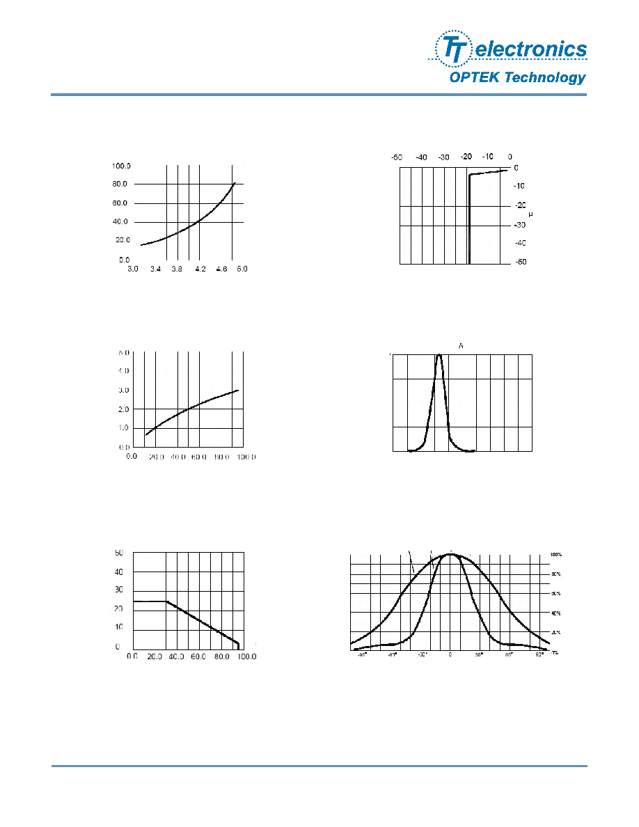
Typical Electro-Optical Characteristics Curves
Maximum Forward DC Current vs Ambient
Temperature
mA
∞C
Far Field Pattern
50% Power Angle: H-H: 110∞ V-V: 50∞
V-V
H-H
Relative Luminous Intensity vs Forward Current
mA
%
Forward Current vs Forward Voltage
V
mA
Reverse Current vs Reverse Voltage
V
A
100
175
50
25
0
%
300
400 500
600
700
800
Relative Luminous Intensity vs Wavelength
mA
Half Power WL = 28nm