2001-07-05
1
OPTO SEMICONDUCTORS
MARKERlight
OS-ML01A
Data Sheet
Besondere Merkmale
∑
Homogen ausgeleuchtete Fl‰che mit hoher
Leuchtdichte
∑
Minimale W‰rmeentwicklung
∑
Flache Bauhˆhe, geeignet f¸r geringe Auf-
/Einbaumˆglichkeiten
∑
Verf¸gbar in verschiedenen Farben und in
weiþ
∑
OSRAM Hyper SIDELED
Æ
ermˆglichen hohe
Lichtleistung
Features
∑
Homogeneously illuminated area with high
luminance
∑
Low heat generation
∑
Flat design, suitable for installation where
space is limited
∑
Available in several colors incl. White
∑
OSRAM Hyper SIDELED
Æ
allow high lumi-
nous flux
Anwendungen
∑
Wegmarkierung
∑
Stufenmarkierung
∑
Wandeinbauleuchte
∑
Hinterleuchtung von Informationen
∑
Sitzplatzmarkierung: (z.B. Theater, Kino)
∑
Hinterleuchtung von Zahlen, Buchstaben
oder Symbolen
∑
Designleuchte
- f¸r Mˆbel
- Ambiente-Leuchten
∑
Allgemeinbeleuchtung
Applications
∑
Road Markers
∑
Step Markers
∑
Markers for walls
∑
Backlighting for Information Panels
∑
Seat-markings: (e.g. Theater, Cinema)
∑
numbers, letters or symbols
∑
Design Lights
- for furnitures
- ambient lights
∑
General Lighting
OS-ML01A
2001-07-05
3
OPTO SEMICONDUCTORS
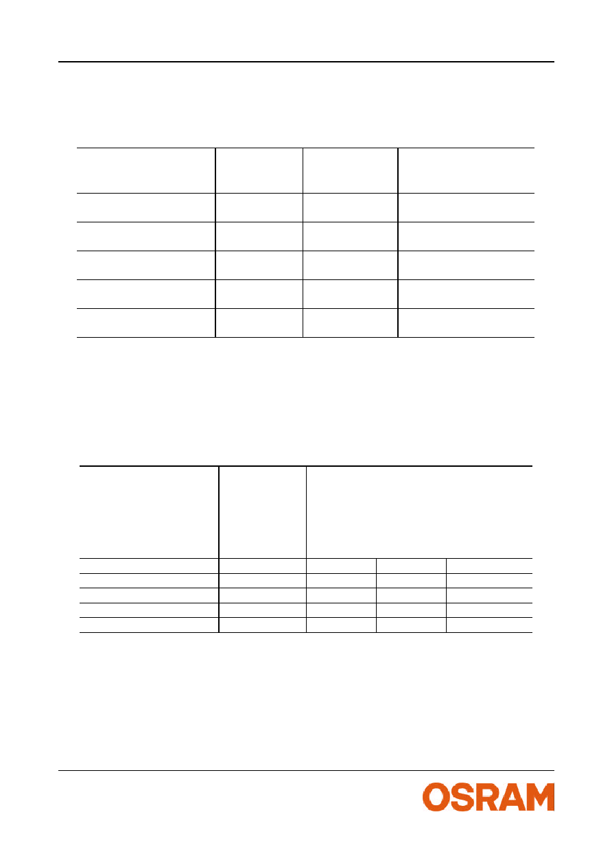
Grenzwerte
Maximum Ratings
Bezeichnung
Parameter
Symbol
Symbol
Werte
Values
Einheit
Units
Temperatur am T
c
-Messpunkt
Temperature on test point
T
c
-30 ... +65
-22 ....+149
∞C
F
Lagertemperatur
Storage temperature range
T
stg
-30 ... +65
-22 ....+149
∞C
F
Maximale Spannung
Maximum voltage
V
max
10,5
V
DC
Sperrspannung
Reverse Voltage
V
R
10,5
V
DC

OS-ML01A
2001-07-05
4
OPTO SEMICONDUCTORS
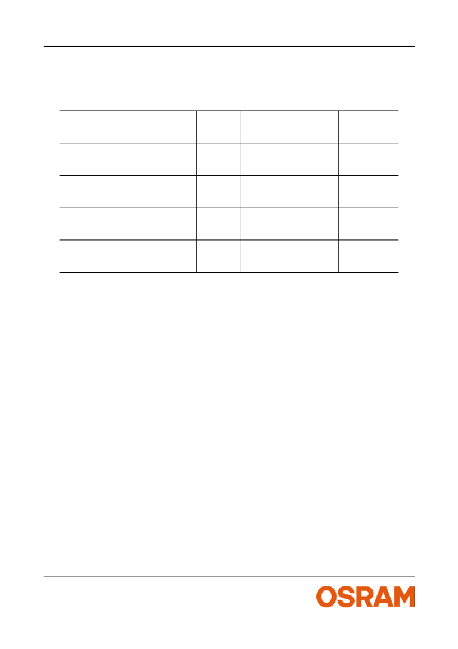
Konstruktionshinweise f¸r Leuchtenhersteller
∑
Kontaktierung durch Anlˆten von Zuleitungen oder Steckverbinder von BJB Leitung
P/C2 oder C2 nur an den vorgesehenen Lˆtpads (beschriftet mit 10V + / -)
∑
Das Modul selbst ist nicht gegen Feuchtigkeit oder Staub gesch¸tzt ( IP 20 ). Die
Leuchte ist der geforderten Schutzart des Gesamtsystems konstruktiv anzupassen.
∑
Die Lichtaustrittsfl‰che ist gegen mechanische und chemische Einfl¸sse zu sch¸tzen.
∑
Die Montage des Moduls erfolgt mittels der vorgesehenen Montagelˆcher. Bei einer
Schraubenmontage m¸ssen Kunststoffunterlegscheiben zwischen Schraubenkopf und
Leiterplatte eingelegt werden, um eine Besch‰digung der Leiterbahnen zu verhindern
∑
Die Temperatur des Moduls sollte im thermisch eingeschwungenen Zustand mittels
eines temperaturempfindlichen Aufklebers am gekennzeichneten Meþpunkt getestet
werden. Die ermittelte Temperatur erlaubt einen direkten R¸ckschluss auf die mˆgliche
Umgebungstemperatur f¸r die Leuchte und die zu erwartende Lebensdauer. Bezugs-
quelle f¸r den Aufkleber ist z.B.
http://www.rs-components.de
Information for construction
∑
Contact with soldering wires or with BJB-conector Lead wire C2 or P/C2 should only be
done on the designated solder pads (marked with 10V +/-)
∑
The module itself is not protected against humidity or dust (IP 20). The construction of
the luminaire should ensure, that the complete system is protected from these external
factors in according with European Standards.
∑
The lighted-surface should be protect against mechanical and chemical influences.
∑
The mounting of the module is carried out by attaching it at the mounting holes. Moun-
ting screws have to be treated with synthetic washers to protect tracks against
damage.
∑
The temperature of the module should be measured in thermal balanced conditions
with the assistance of a temperature sensitive sticker on the defined testing point. The
measured temperature indicates a direct conclusion of the allowed temperature sur-
rounding the luminaire and the expected life time of the module. One possible supplier
of the sticker is
http://www.rs-components.de
OS-ML01A
2001-07-05
5
OPTO SEMICONDUCTORS
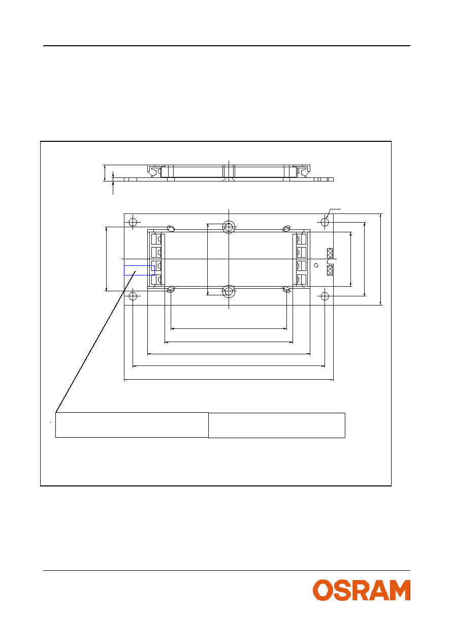
Technische Zeichnung
Technical drawing
(Maþe in mm / measures in mm)
+
-
1
0
V
52 ±0.1
85 ±0.35
3
7
±
0
.
3
5
2
2
±
0
.
2
5
66.5 ±0.1
6
.
7
±
0
.
2
3
0
±
0
.
1
5
78 ±0.15
47±0.15
1
.
5
2
6
.
7
±
0
.
1
2
9
±
0
.
1
¯3.1
Bereich f¸r Temperatur empfindlichen
Aufkleber = Tc ≠ Punkt (max. 5 x 12mm)
Area for temperatur sensitive label
= T
c
≠ point (max. 5 x 12mm)