 | ÐлекÑÑоннÑй компоненÑ: AN7017S | СкаÑаÑÑ:  PDF PDF  ZIP ZIP |
Äîêóìåíòàöèÿ è îïèñàíèÿ www.docs.chipfind.ru

ICs for FM/AM Tuner
s
Overview
The AN7017S and the AN7017SB are the ICs incorpo-
rating FM/TV front-end most suitable for headphone
stereo.
Sealed in a 16-pin flat package, the chip operates sta-
bly at TV band (170MHz ~ 222MHz) FM band (76MHz ~
108MHz).
RF amplifiers and oscillations are provided in FM/TV
band individually, and are designed most suitably. So
both characteristics of FM/TV band are satisfied.
s
Features
·
Low current consumption
·
Band switching circuit built-in
·
A single chip integrating FM/TV band
·
IF amp. built-in
AN7017S, AN7017SB
FM/TV Front-end ICs for 1.5V Headphone Stereo, Radio Cassette Recorder
16
15
14
13
12
11
10
9
1
2
3
4
5
6
7
8
GND
V
CC1
GND
FM
RF
Amp.
TV
RF
Amp.
FM
L OSC
TV
L OSC
Mix.
IF Amp.
TV/
FM
SW
V
CC2
s
Block Diagram
0.1
±
0.1
1.5
±
0.2
0.3
0.65
0.15
0.4
1
2
3
4
5
6
7
8
16
15
14
13
12
11
10
9
0.4
±
0.25
1.27
Unit : mm
6.5
±
0.3
4.2
±
0.3
10.1
±
0.3
AN7017S
16-Lead SOP Package (SOP016-P-0225)
0.8
0.1
±
0.1
1.5
±
0.2
0.35
±
0.1
0.5
0.65
0.15
1
8
16
9
Unit : mm
6.5
±
0.3
6.3
±
0.3
4.3
±
0.3
AN7017SB
16-Lead SOP Package (SSOP016-P-0225a)
ICs for FM/AM Tuner
AN7017S, AN7017SB
s
Characteristics Curve
V
CC
I
CC
P
D
T
opr
T
stg
Supply Voltage
Supply Current
Power Dissipation
Operating Ambient Temperature
Storage Temperature
V
mA
mW
°C
°C
Parameter
Symbol
Rating
Unit
s
Absolute Maximum Ratings
(Ta=25°C)
2.5
10
30
22 ~ + 75
55 ~ + 125
Parameter
Symbol
Range
s
Recommended Operating Range
(Ta=25°C)
Operating Supply Voltage Range
V
CC
1V ~ 2V
Parameter
Symbol
Condition
min.
typ.
max.
Unit
s
Electrical Characteristics
(V
CC
=1.2V, Ta = 25°C)
No Signal Current
Conversion Gain
Oscillation Voltage
S/N
No Signal Current
Conversion Gain
Oscillation Voltage
S/N
FM
TV
I
tot
(FM)
G
conv
(FM)
V
OSC
(FM)
S/N (FM)
I
tot
(TV)
G
conv
(TV)
V
OSC
(TV)
S/N (TV)
Note)
V
CC
=1V
V
in
= 60dB
µ
2.5
31
73
55
3.2
27
57
53
mA
dB
mV
dB
mA
dB
mV
dB
Note)
V
CC
=1V
V
in
=60dB
µ
Note) Conversion Gain= 20log (
V
(
µ
V)
÷
100)
V is output difference at 40dB
µ
and 46dB
µ
.
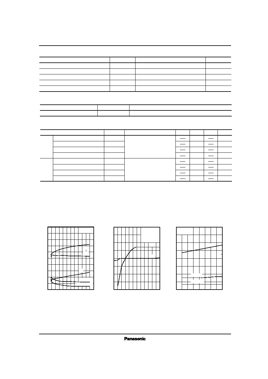
Supply Voltage Characteristics (FM)
Oscillation Frequency Deviation
S/N, S/N Sensitivity, Limiter Sensitivity, I
tot
0
0
50
60
70
80
90
100
1.0
V
CC
(V)
L
i
m
i
t
S
e
n
s
(
d
B
µ
)
,
S
/
N
S
e
n
s
(
d
B
µ
)
,
S
/
N
(
d
B
)
40
30
20
10
1.2 1.4 1.6 1.8 2.0 2.2 2.4 2.6 2.8 3.0
2
1
0
1
2
3
4
3
2
I
t
o
t
(
m
A
)
f
s
i
f
t
×
1
0
2
(
k
H
z
)
S/N
f
sift
Input/Output Characteristics
S/N, V
out
0
50
40
30
20
10
0
20
V
in
(dB
µ
)
V
o
u
t
(
d
B
)
60
40
60
80
100
60
50
40
30
20
10
0
S
/
N
(
d
B
)
V
out
120
0
0
20
30
40
50
60
70
78
Frequency f
in
(MHz)
S
/
N
S
e
n
s
(
d
B
µ
)
,
L
i
m
i
t
S
e
n
s
(
d
B
µ
)
10
82
86
90
100
50
0
V
O
S
C
(
m
V
)
98
Frequency Characteristics
(FM) V
OSC
, S/N Sensitivity,
Limiter Sensitivity
102 106
94
80
V
CC
= 1.2V
Ta = 25°C
V
OSC
V
CC
= 1.5V
f
in
= 78MHz
30% Mod.
Ta = 25°C
Ta =25°C
S/N Sens
S/N Sens
Limit Sens
S/N
I
tot
Limiter Sens
ICs for FM/AM Tuner
AN7017S, AN7017SB
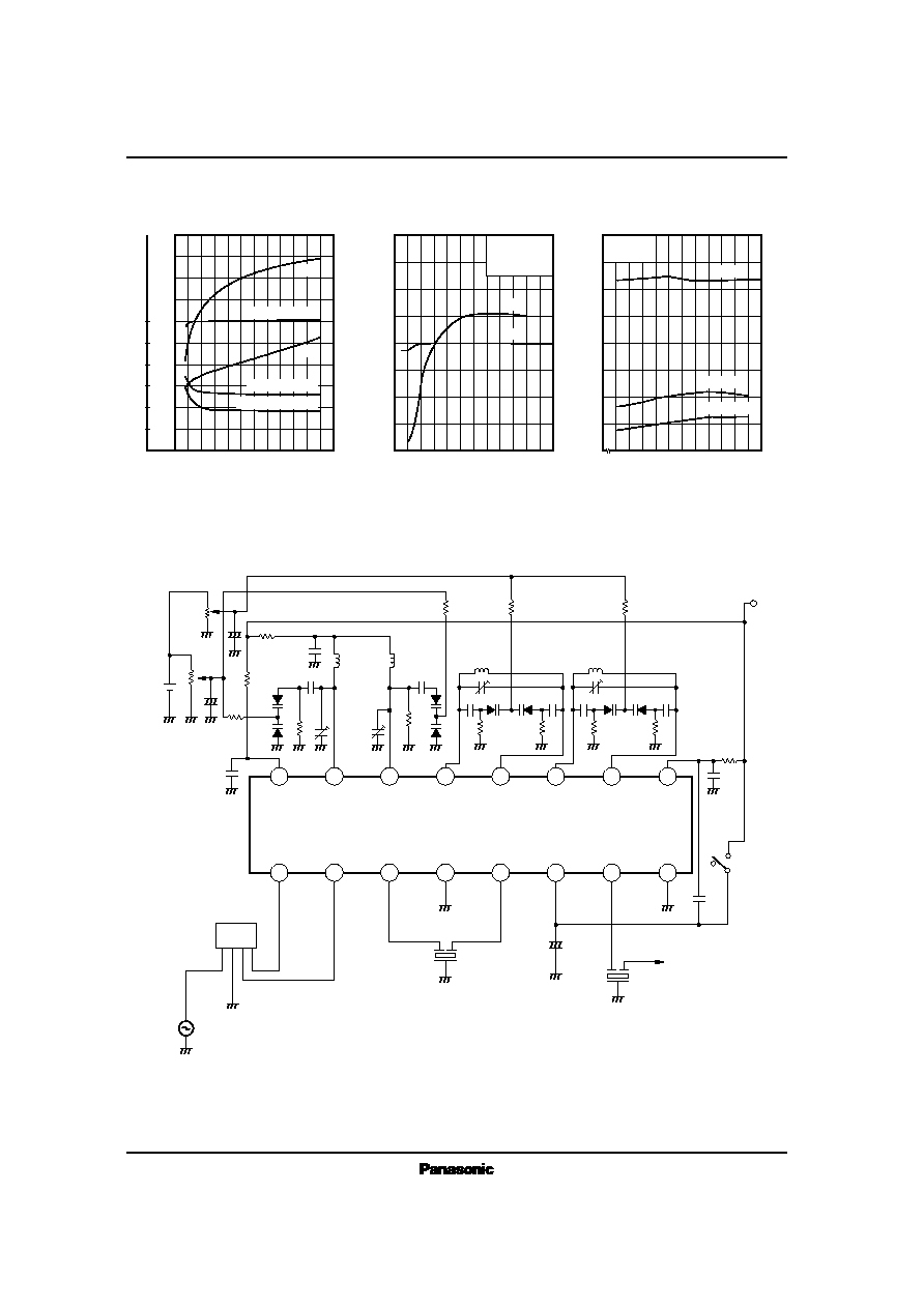
Supply Voltage Characteristics (TV)
Oscillation Frequency Deviation
S/N, S/N Sensitivity, Limiter Sensitivity, I
tot
0
50
60
70
80
1.0
V
CC
(V)
L
i
m
i
t
S
e
n
s
(
d
B
µ
)
,
S
/
N
S
e
n
s
(
d
B
µ
)
,
S
/
N
(
d
B
)
40
30
20
10
1.2 1.4 1.6 1.8 2.0 2.2 2.4 2.6 2.8 3.0
2
1
0
1
2
3
f
s
i
f
t
×
1
0
2
(
k
H
z
)
Input/Output Characteristics
(TV) S/N, V
out
0
50
40
30
20
10
0
30
V
in
(dB
µ
)
V
o
u
t
(
d
B
V
)
V
CC
=1.5V
f
in
=180MHz
305% Mod.
60
50
70
90
110
60
50
40
30
20
10
0
S
/
N
(
d
B
)
S/N
V
out
20
40
60
80
100
120
10
0
20
30
40
50
60
70
176
Frequency f
in
(MHz)
L
i
m
i
t
S
e
n
s
(
d
B
µ
)
,
S
/
N
S
e
n
s
(
d
B
µ
)
10
180 184
196
100
50
0
V
O
S
C
(
m
V
)
V
OSC
208
Frequency Characteristics
(TV) V
OSC
, S/N Sensitivity,
Limiter Sensitivity
212
220
200
V
CC
=1.2V
Limit Sens
3
4
5
I
t
o
t
(
m
A
)
1
6
5
4
3
2
188 192
204
216
Limit Sens (3dB)
S/N Sens (30dB)
S/N (V
in
= 60dB)
f
sift
I
tot
S/N Sens
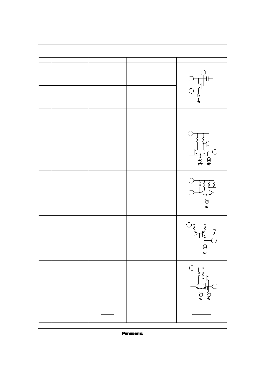
s
Application Circuit
16
15
14
13
12
11
10
9
1
2
3
4
5
6
7
8
+
+
2
0
0
k
2
0
0
k
1
µ
F
10V
1
µ
F
470k
100
0.01
µ
F
10
200pF
1
0
0
k
1
2
p
F
0.01
µ
F
1
0
0
k
12pF
12pF
470k
470k
470k
47pF
0.001
µ
F
3
3
0
p
F
100k
100k
100k
100k
1
0
0
p
F
12pF
0.001
µ
F
V
CC
=1.2V
10
0
.
0
1
µ
F
FM
TV
0
.
0
2
2
µ
F
to IF IC
1
µ
F
SFE10.7MA5
SFE10.7MA5
BPF
FM SG
AN7017S, AN7017SB
FM Antenna Coil : Internal diameter 2.5mm. Lead diameter 0.35mm 11T Variable Capacitance : SVC203CP (SANYO)
FM Oscillation Coil : Internal diameter 2.5mm. Lead diameter 0.35mm 13T Ceramic Filter : SFE10.7MA5 (MURATA)
TV Antenna Coil : Internal diameter 2.5mm. Lead diameter 0.35mm 3T Band Pass Filter : TVSB4 (SOUSHIN)
FM Oscillation Coil : Internal diameter 2.5mm. Lead diameter 0.35mm 4T IF Amp. : AN7236 (Panasonic)
ICs for FM/AM Tuner
AN7017S, AN7017SB
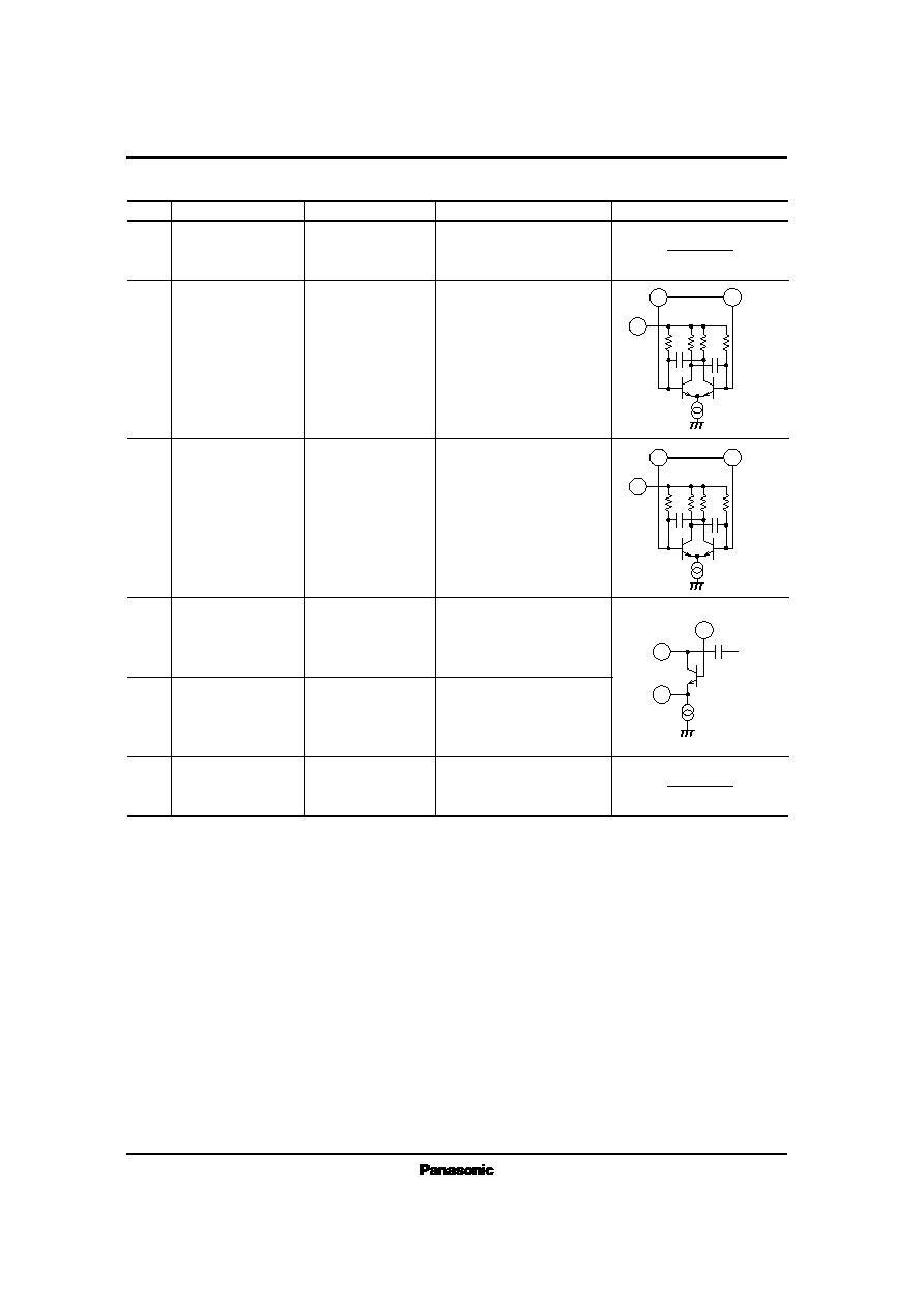
Equivalent Circuit
Description
Typ.Waveform
Pin No.
1
Pin Name
FM RF Input
FM signal
FM RF input pin
15
FM RF Output
FM signal
FM RF output pin
4
GND
DC 0V
8
GND
7
IF Output
IF output pin
6
TV/FM switch
5
IF Input
IF input pin
3
Mix. Output
10.7MHz
IF signal
10.7MHz
IF signal
10.7MHz
IF signal
TV/FM switching
At FM, stop the
current source of TV
circuit by connecting
Pin6 to V
CC
,
and at
TV, stop the current
source of FM circuit by
opening this.
GND pin
Used for IF
amp. /oscillation circuit
current source
Mix. output pin
Ceramic Filter connect
to output.
GND pin
Used for RF
amp. /Mixer.
1
15
16
7pF
16
3
9
5
5k
5
k
2
.
2
k
2
.
2
k
9
6
FM
TV
16
7
s
Pin Descriptions
ICs for FM/AM Tuner
AN7017S, AN7017SB
s
Pin Descriptions (Cont.)
Equivalent Circuit
Description
Typ.Waveform
Pin No.
Pin Name
16
V
CC1
DC 1.5V
10
·
11
TV OSC
TV OSC pin
9
V
CC2
DC 1.5V
Supply voltage pin
Used for IF
amp. /oscillation circuit
current source
2
TV RF Input
TV signal
TV RF input pin
12
·
13
FM OSC
FM OSC pin
65MHz ~ 96MHz
oscillation
14
TV RF Output
TV signal
TV RF output pin
Supply voltage pin
Used for RF amp.,
mixer
160MHz ~ 216MHz
oscillation
2
14
16
7pF
11
9
7pF
7pF
1
0
k
2
7
0
1
0
k
2
7
0
10
13
9
7pF
7pF
1
0
k
2
7
0
1
0
k
2
7
0
12