ICs for Audio Common Use
1
AN7077Z
Power supply and boost IC for class-H power amplifier
s
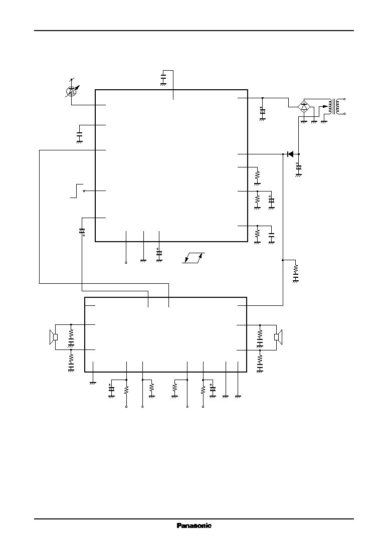
Overview
A BTL 50 W
◊
2-channel (maximum. 75 W
◊
2-
channel) class-H power amplifier can be made up by com-
bining the power supply boost amplifier AN7077Z and
the single power supply BTL audio power amplifier
AN7194Z, and it is possible to make a low consumption
power system.
s
Features
∑
Incorporating various protection circuits
∑
Built-in standby circuit
∑
Peak detection circuit : Limits class-H operation at high
frequency
∑
Built-in timer circuit
If a current larger than allowable value continues to flow
into the power supply transformer, this circuit stops the
class-H operation to prevent the transformer from dam-
age by a fire.
∑
Built-in mute function
∑
Built-in LED driver
s
Applications
∑
Miniature audio component, CD player radio cassette,
karaoke and other audio equipment
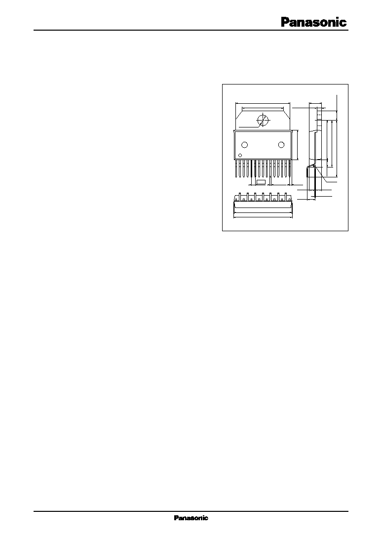
HZIP015-P-0745A
Unit : mm
18.00
±
0.30
13.50
±
0.30
3.60
±
0.10
10.0
±
0.30
1
15
4.00
±
0.20
1.50
±
0.10
0.50
+
0.20
-
0.10
(0.61)
(2.54)
0.25
+
0.15
-
0.05
R0.55
3.25
±
0.10
13.25
±
0.30
18.95
±
0.50
15.65
±
0.50
1.27
(1.80)
(1.95)
19.00
±
0.30
19.30
±
0.30
2.40
±
0.50

3
ICs for Audio Common Use
AN7077Z
s
Electrical Characteristics at V
CCH
=
24.0 V, V
CCL
=
12 V, frep.
=
1 kHz, T
a
=
25
∞
C
s
Absolute Maximum Ratings
Parameter
Symbol
Rating
Unit
Supply voltage
*2
V
CC
34
V
Supply current
I
CC
9.0
A
Power dissipation
*3
P
D
68.2
W
Operating ambient temperature
*1
T
opr
-
25 to
+
75
∞
C
Storage temperature
*1
T
stg
-
55 to
+
150
∞
C
s
Recommended Operating Range
Parameter
Symbol
Range
Unit
Supply voltage
V
CC
10.0 to 28.0
V
Parameter
Symbol
Conditions
Min
Typ
Max
Unit
Quiescent current
I
CQ
V
IN
=
open
25
50
mA
Standby current
I
STB
V
IN
=
open
1
10
µ
A
Output offset voltage 1
V
OFF1
V
IN
=
8 V, R
L
=
4
2.0
2.5
3.0
V
Output offset voltage 2
V
OFF2
V
IN
=
16 V, R
L
=
4
2.5
3.0
3.5
V
Output current
I
OUT
V
IN
=
14 V, R
L
=
2
7.0
8.0
A
Voltage gain
G
V
V
IN
=
3 V
rms
(DC 15 V), R
L
=
4
-
1.0
0.0
1.0
dB
Pin 4 output current
I
DET
I
OUT
=
2 A
150
190
230
µ
A
Pin 5 output current 1
I
TI1
Pin 4
=
high, pin 5
=
3 V
13
15
17
µ
A
Pin 5 output current 2
I
TI2
Pin 4
=
low, pin 5
=
3 V
4.5
5
5.5
µ
A
LED output current
I
LED
V
IN
=
1 V
rms
(DC 16 V), V
LED
=
8 V
15
30
mA
Standby terminal current
I
CQ-STB
V
IN
=
open, V
STB
=
5 V
500
650
800
µ
A
Note) *1 : T
a
=
25
∞
C except operating ambient temperature and storage temperature.
*2 : Without input signals (output current 0 mA).
*3 : The value when R
th(j-c)
=
1.1
∞
C/W, T
a
=
75
∞
C.

4
AN7077Z
ICs for Audio Common Use
s
Usage Notes
1. Always attach an outside heat sink to use the chip. In addition, the outside heat sink must be fastened onto a chassis
for use.
2. Connect the radiation fin to GND potential.
3. Avoid short circuit to V
CC
and short circuit to GND, and load short-circuit
4. The thermal protection circuit will be actuated at T
J
=
approx. 145
∞
C, but it is automatically reset when the chip
temperature drops below the above set level.
5. The overvoltage protection circuit starts its operation at V
CC
=
approx. 36 V.
6. The protection circuit between V
CC
and the output starts its operation when the V
CC
-
output voltage
=
approx. 18 V.
7. For the standby voltage, use a stabilized power supply of 3 V or more.
s
Technical Information
∑
P
D
T
A
curves of HZIP015-P-0745A
P
D
T
A
0
0
20
40
60
80
100
120
25
50
75
Ambient temperature T
a
(∞
C)
Allo
w
able po
wer dissipation P
D
(W)
100
125
150
Without heat sink
10
∞
C/W heat sink
5
∞
C/W heat sink
3
∞
C/W heat sink
2
∞
C/W heat sink
1
∞
C/W heat sink
Infinite heat sink
R
th(j-c)
=
1.1
∞
C/W
R
th(j-a)
=
68.3
∞
C/W
113.6
59.5
40.3
30.5
20.5
11.3
1.8