
ICs for FM/AM Tuner
1
s
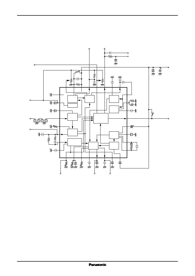
Block Diagram
AN7293NFBQ
FM-IF, NC, MPX IC for Car Radio
s
Overview
The AN7293NFBQ is an IC having FM-IF, NC and
MPX function for car radio. A tuner block of car radio can
be constructed by this IC and the AN7289NFBQ/NSC.
s
Features
∑
A less number of external components is required (8
components reduction compared with our conventional
IC)
∑
Neighbering-station interference characteristics im-
provement by band-ATC function
∑
Band-mute on/off function
∑
DIL package product (the AN7293NSC) is also available
s
Applications
∑
Car radios
7.0±0.3
(0.55)
1.4±0.2
0.625±0.100
0.625±0.100
0.1±0.1
9.2±0.4
7.0±0.3
0.8
9.2±0.4
0.3
+0.10 ≠0.05
0.15
+0.10 ≠0.05
1
8
24
17
9
16
32
25
Unit: mm
SSOP032-P-0375
F
orced mono
A
TC-Adj.
SEP-Adj.
R-Out
L-Out
Mute-Adj.
SD-Adj.
AFC
ST
-Ind.
Mono: high
Stereo: lo
w
24
23
22
21
20
19
18
17
1
2
3
4
5
6
7
8
25
26
27
28
29
30
31
32
16
15
14
13
12
11
10
9
V
REF
IF-In
V
S
Out
V
BAND
IF
det.
IF
limiter
Level
det.
Multipath
det.
Band-det.
SD
IF-counter
Mute
PNL
Noise
det.
Demod.
VCO
PLL
Pilot
det.
GND
V
REF
V
CC

AN7293NFBQ
ICs for FM/AM Tuner
2
s
Pin Description
Pin No.
Description
17
Detection output
18
PNL output hold
19
SD/FM-IF counter output/stereo indicator
20
SD sensitivity adjustment
21
AFC voltage
22
V
CC
23
FM detection
24
Soft mute adjustment
25
GND
26
V
REF
27
IF bypass
28
IF input
29
Control voltage adjustment
30
Control voltage
31
Multi-path noise input
32
Multi-path detection
Pin No.
Description
1
ASC adjustment/forced monaural
2
ATC adjustment
3
Separation adjustment
4
ATC low-pass filter
5
R-ch. output
6
L-ch. output
7
Mute voltage
8
Pilot detection low-pass filter
9
PLL low-pass filter
10
PLL low-pass filter
11
VCO
12
Pilot cancel control low-pass filter
13
Band signal output/band mute SW
14
PNL low-pass filter
15
PNL AGC
16
PNL input
Parameter
Symbol
Rating
Unit
Supply voltage
V
CC
9.1
V
Supply current
I
CC
45
mA
Power dissipation
*2
P
D
343.3
mW
Operating ambient temperature
*1
T
opr
-
30 to
+
80
∞
C
Storage temperature
*1
T
stg
-
55 to
+
125
∞
C
s
Absolute Maximum Ratings
Note) *1: Except for the power dissipation, operating ambient temperature, and storage temperature, all ratings are for T
a
=
25
∞
C.
*2: T
a
=
80
∞
C
s
Recommended Operating Range
Parameter
Symbol
Range
Unit
Supply voltage
V
CC
7.2 to 9.0
V
ICs for FM/AM Tuner
AN7293NFBQ
3
s
Electrical Characteristics at T
a
=
25
∞
C
Unless otherwise specified, V
CC
=
8V, V
IN1
is f
=
10.70 MHz, Mod. = 1 kHz, 30%
FM modulation stereo input is L
+
R
=
90% V
P
=
10%
Parameter
Symbol
Conditions
Min
Typ
Max
Unit
Control voltage (1)
V
C1
Without signal input, pin 30 DC voltage
0.0
0.3
0.9
V
Control voltage (2)
V
C2
V
IN1
=
40 dB
µ
, pin 30 DC voltage
0.6
1.3
1.6
V
Control voltage (3)
V
C3
V
IN1
=
70 dB
µ
, pin 30 DC voltage
2.4
3.1
3.8
V
Control voltage (4)
V
C4
V
IN1
=
100 dB
µ
, pin 30 DC voltage
4.5
5.3
5.8
V
Control voltage (5)
V
C5
V
C5
=
V
C3
-
V
C2
1.8
2.0
2.2
V
Control voltage (6)
V
C6
V
C6
=
V
C4
-
V
C3
1.85
2.05
2.25
V
Output level L-channel
V
OL
V
IN1
=
70 dB
µ
, pin 6 AC voltage
85
105
125
mV[rms]
Output level R-channel
V
OR
V
IN1
=
70 dB
µ
, pin 5 AC voltage
85
105
125
mV[rms]
Channel balance
CB
CB
=
20∑log (V
OL
/V
OR
)
-
1.0
0
1.0
dB
Residual pilot voltage
V
PC
V
P
=
10
%
modulation, V
IN1
=
70 dB
µ
,
4
14
mV[rms]
pin 18 output voltage
Stereo lamp light up level
LAMP
ON
19 kHz modulation, Modulation factor
1.3
4.0
6.3
%
at which pin 19 becomes under 1 V
Separation L-channel
Sep
L
L
+
R
=
90
%
, V
P
=
10
%
25
33
dB
Larger separation value after
Separation R-channel
Sep
R
changing over pin 3 external resistor
25
33
dB
Capture range
CR
Modulation at V
P
=
6.5%
±
0.4
±
0.7
%
Referred to 19 kHz
Counter output level (1)
VIF
1
V
IN1
=
100 dB
µ
, V
20
=
2 V
135
155
175
mV[rms]
pin 19 output voltage
Counter output level (2)
VIF
2
V
IN1
=
100 dB
µ
, V
20
=
5 V
0
2
5
mV[rms]
pin 19 output voltage
Monaural THD (L)
THD
L
V
IN2
monaural input, 500 mV[0-p]
0.1
0.3
%
1 kHz, L-ch. output distortion factor
Monaural THD (R)
THD
R
V
IN2
monaural input, 500 mV[0-p]
0.1
0.3
%
1 kHz, R-ch. output distortion factor
Stereo THD (L)
THD
STL
V
IN2
stereo input, 500 mV[0-p]
0.1
0.3
%
1 kHz, L-ch. output distortion factor
Stereo THD (R)
THD
STR
V
IN2
stereo input, 500 mV[0-p]
0.1
0.3
%
1 kHz, R-ch. output distortion factor
PNL-AGC voltage (1)
V
AGC1
V
IN2
=
Without input
1.2
1.4
1.7
V
pin 15 DC voltage
PNL-AGC voltage (2)
V
AGC2
V
IN2
=
100 mV, f
=
100 kHz input
0.1
0.35
0.60
V
Difference from V
AGC1
Residual noise voltage
V
NR
V
IN2
=
(pulse width 10
µ
s, 1 V[p-p]
0.0
0.2
0.7
mV[rms]
1 kHz) L-ch. output

AN7293NFBQ
ICs for FM/AM Tuner
4
s
Electrical Characteristics at T
a
=
25
∞
C (continued)
Unless otherwise specified, V
CC
=
8V, V
IN1
is f
=
10.70 MHz, Mod. = 1 kHz, 30%
FM modulation stereo input is L
+
R
=
90% V
P
=
10%
Parameter
Symbol
Conditions
Min
Typ
Max
Unit
SD sensitivity
SD
S
V
IN1
when V
20
=
2 V, V
19
>
2 V
70
80
90
dB
µ
SD bandwidth
SD
W
V
IN
bandwidth when V
24
=
2 V,
100
130
160
kHz
and V
19
>
2 V, V
IN1
=
100 dB
µ
Supply current
I
TOT
Without input
30
37
44
mA
Limiting sensitivity
V
LIM
V
IN1
input level when pin 5 AC
24
32
38
dB
µ
voltage drops by 3 dB
ATC
V
ATC
L-ch. output ratio when
7
11
15
dB
V
2
=
2 V and 0 V
Gate pulse width
PW
V
IN2
=
(pulse width 1
µ
s, 0.3 V[p-p]
16
23
30
µ
s
1 kHz) pin 18 output pulse width
∑
Design reference data
Note) The following characteristics are the reference values for design and not guaranteed values.
Parameter
Symbol
Conditions
Min
Typ
Max
Unit
Stereo lamp turn off level
LAMP
OFF
Ratio between the modulation factor
2.0
6.0
10.0
dB
when pin 19 becomes 2 V or more
and LAMP
ON
AFC offset voltage
V
AFC
Without signal input, DC potential
-
0.1
0.0
0.1
V
difference between pin 21 and pin 26.
ICs for FM/AM Tuner
AN7293NFBQ
5
s
Application circuit Example
F
orced mono
A
TC-Adj.
ASC-Adj.
SEP-Adj.
R-Out
L-Out
Mute-Adj.
AFC
ST
-Ind.
Mono: high
Stereo: lo
w
24
23
22
21
20
19
18
17
1
2
3
4
5
6
7
8
25
26
27
28
29
30
31
32
16
15
14
13
12
11
10
9
V
REF
IF-In
V
S
Out
V
BAND
V
CC
50 k
50 k
10 k
0.1
µ
F
0.01
µ
F
0.022
µ
F
0.022
µ
F
0.1
µ
F
0.1
µ
F
0.1
µ
F
1
µ
F
0.1
µ
F
0.047
µ
F
0.47
µ
F
912kHz
10 k
330 k
100
µ
F
0.1
µ
F
0.1
µ
F
0.01
µ
F
0.01
µ
F
0.1
µ
F
680 pF
470 pF
50 k
2.2 k
180 pF
100 k
100 k
10 k
IF-Counter
SD
SD-Adj.
Seek/Lamp
ST-Lamp: high (4.5 V or more)
Seek: Open
0.1
µ
F
GND
V
S
-Adj.
0.1
µ
F
0.01
µ
F
Ms 3 Ms 3
0.022
µ
F
50 k
100 k
330 k
V
CC
1000pF
IF
det.
IF
limiter
Level
det.
Multipath
det.
Band-det.
SD
IF-counter
Mute
PNL
Noise
det.
Demod.
VCO
PLL
Pilot
det.
V
REF