 | –≠–ª–µ–∫—Ç—Ä–æ–Ω–Ω—ã–π –∫–æ–º–ø–æ–Ω–µ–Ω—Ç: AN8267S | –°–∫–∞—á–∞—Ç—å:  PDF PDF  ZIP ZIP |

s Overview
The AN8267S is an IC to drive the brushless DC fan motors
for internally cooling or blowing the air to the office automa-
tion equipments and measuring equipmennts.
s Features
∑
Operating supply voltage range ; V
CC
=9.6 to 27.6V
(Operable at V
CC
=6V to 9.6V as well)
∑
2-phase half-wave drive, built-in power transistor
∑
Built-in lock protective function and automatic reset function
∑
Built-in thermal protective circuit (operating temperature:
150∞C typ.)
∑
Built-in rotation display function
s Application
For drive of brush-less DC fan motor
AN8267S
Fan Motor Driver
0.1
±
0.1
(0.4)
0.9
±
0.25
2.05
±
0.2
0.9
±
0.25
0.2
+ 0.1 ≠ 0.05
(0.4)
0.4
±
0.25
1.27
2
3
4
5
6
7
8
1
16
15
14
13
12
11
10
9
Unit : mm
7.6
±
0.3
5.5
±
0.3
1.16-pin PANAFLAT Plastic Package (SOP016-P-0300)
10.09
±
0.3
13
2
3
7
9
8
11
10
6
4
12
14
1
16
5
Hall Bias
TSD
Revolution
Display
CTRL
Lock Protect
Automatic Reset
+
≠
Hall
Amp.
PGND
VM
C
GND
RD
1
RD
2
B
1
B
2
OUT
2
OUT
1
TSD
V
S
V
CC
IN (+)
IN (≠)
s Block Diagram

V
CC
I
CC
I
O (peak)
I
2
, I
3
V
2
, V
3
, V
6
, V
10
P
D
T
opr
T
stg
Supply voltage
Supply current
Output current (t=0.1s )
Circuit current (Inflow current)
Circuit voltage (Applied voltage)
Power dissipation
Operating ambient temperature
Storage temperature
V
mA
A
mA
V
mW
∞C
∞C
Parameter
Symbol
Rating
Unit
s Absolute Maximum Ratings (Ta=25∞C)
28.8
18
1.5
10
55
735
Note 1)
≠30 to + 80
≠55 to + 150
Note 1) When mounted to the glass epoxy PCB 50
◊
50
◊
0.8mm
Parameter
Symbol
Range
s Recommended Operating Range (Ta=25∞C)
Operating supply voltage range
V
CC
9.6V to 27.6V
Parameter
Symbol
Condition
min
typ
max
Unit
s Electrical Characteristics (Ta=25∞C)
Supply current
I
CC
17
mA
V
CC
=12V, RL=OPEN
Hall amp./Common mode input voltage
2
V
HI
V
CC
≠2
V
Input current
I
IH
50
µ
A
V
CC
=12V, V
HI
=2V
Hall bias voltage
4
V
HB
6
V
V
CC
=12V, I
HB
=≠5mA
V
CC
=12V, I
O
=0.5A
V
CC
=12V, V
O
=55V
V
CC
=12V, V
4
=0V
Output saturation voltage
V
Osat
1.4
V
0.9
Leak current
I
Oleak
100
µ
A
Bound protection Ct/Charging current
≠12
Itc
≠7
µ
A
≠9.5
5
Bound protection Ct/Charging current
0.95
Itd
µ
A
1.3
V
CC
=12V, V
4
=4.3V
Threshold value voltage (1)
3.8
Vt
H
4.4
V
4.1
V
CC
=12V, Shut off
1.65
Threshold value voltage (2)
0.6
Vt
L
1.3
V
0.95
V
CC
=12V, Recovered
Rotation display/Output leak current
I
OL3
10
µ
A
V
CC
=12V, V
OL
=55V
Output voltage
V
OL3
0.4
V
V
CC
=12V, I
OL
=5mA
Rotation display/Output leak current
I
OL2
10
µ
A
V
CC
=12V, V
OL
=55V
Output voltage
V
OL2
0.4
V
V
CC
=12V, I
OL
=5mA
13
2
3
7
9
8
11
10
6
4
12
14
1
16
5
TSD
CTRL
+
PGND
VM
C
GND
RD
1
RD
2
B
1
B
2
OUT
2
OUT
1
TSD
V
S
V
CC
V
CC
Hall Bias
Revolution
Display
Lock Protect
Automatic Reset
+
≠
IN (+)
IN (≠)
Hall
Amp.
s Application Circuit

s Supplementary Explanation
∑ Precautions for Using the AN8267S
Observe the following in order to use the AN8267S safely
and properly.
Operating supply voltage range : 9.6V to 27.6V
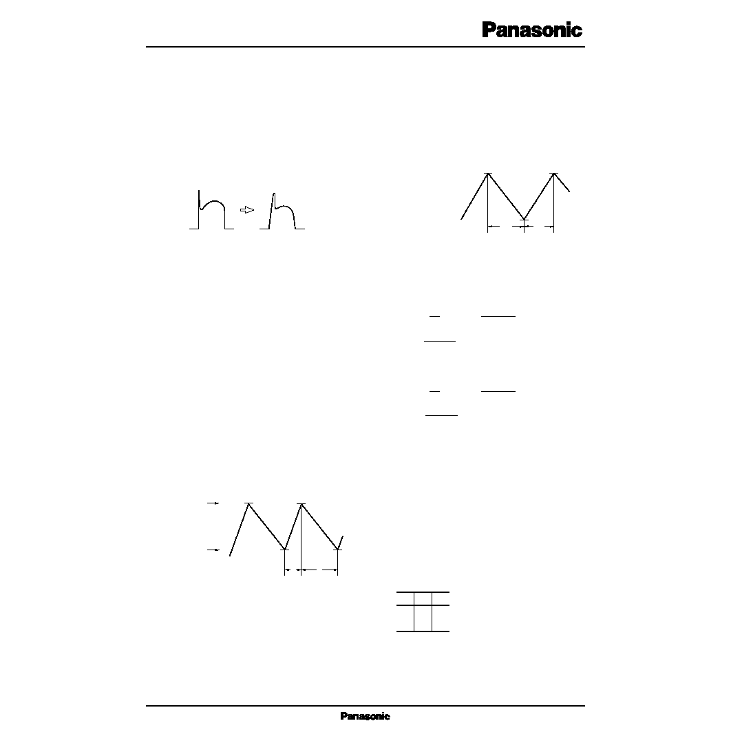
1. Maximum applied voltage to the coil output Pins6 and 10
When driving the motor, the counter electromotive power
of the coil is applied to the coil output Pins6 and 10 when the
output transistor is turned off. (Refer to Fig.1)
With the AN8267S, see to it that this counter electromotive
power will be 55V or less at maximum.
(Suppressing the Counter Electromotive Power)
To suppress the counter electromotive power by the moter
coil to 55V at maximum, do as follows.
1) When using the Zener diode
Connect the Zener diode between the Pin11 of the
AN8267S and the power line. The counter electromotive
power which can be suppressed by the Zener diode is
V
CC
≠V
D
+V
Z
. Since V
CCmax
.=27.6V;V
Zmax.
= 55V≠ 27.6V +
0.7V=28.1V
Therefore, if you keep V
Z
at 28V or less, the counter elec-
tromotive power will not exceed 55V.
2) When using the capacitor
Connect the capacitor between the base and collector of the
coil output transistor as shown in Fig.3.
A capacitor value is as follows. C : 1,000pF to 10,000pF
C : 1000pF--10000pF
This capacitor can dull a rise of the counter electromotive
power of the coil output. Select the capacitor so that maxi-
mum voltage of the counter electromotive power V
max.
will
not exceed 55V.
OFF
55V
max.
Output
Transistor
Hair-shaped Pulse
of Counter Electromotive Power
Fig.1 Coil Output Waveform
Motor Generated
Voltage
ON
OFF
AN8267S
13
16
4
8
6
11
12
Counterflow Preventive Diode
Zener Diode
Hall Element
14
1
10
Fig.2
AN8267S
13
16
4
8
6
11
12
Counterflow Preventive Diode
Hall Element
14
1
10
9
7
Fig.3
Dull a rise
s Pins Descriptions
Pin No.
Pin name
Symbol
1
2
3
4
5
6
7
8
IN (≠)
RD1
RD2
C
TSD
OUT1
B1
P. GND
B2
OUT2
VM
V
CC
GND
VS
NC
IN (+)
Hall input (≠)
Rotation display 1 (pulse output)
Rotation display 2 (H/L output)
Lock protection automatic reset
Thermal shutdown
Motor coil output 1
Output base 1
Power ground
Pin No.
Pin name
Symbol
9
10
11
12
13
14
15
16
Output base 2
Motor coil output 2
Counter electromotive absorption
Supply voltage pin
Ground pin
Hall bias
Hall input (+)
When the lock protective function is being activated, coil
current supply/stop intervals are about 1 : 7 in terms of time
ratio.
Assuming the external capacitor of the Pin4 to be of 1
µ
F,
the supply/stop time ratio is about 0.3sec. : 2sec.
Lock Protective Function ON/OFF Time Calculation Expres-
sion
Assuming the charging current to be Ich and the discharging
current to be I
DC
;
At charge time ;
At discharge time
Each value (typ.) of the AN8267S is ;
V
1
=4V Ich=9.5
µ
A
V
2
=0.95V I
DC
=1.3
µ
A
When C=1
µ
F ;
t
on
=0.32s C : External capacitor's capacity
t
off
=2.35s
4. Rotation output Pins2 and3
The Pins2 and 3 are of open collector output. The Pin2 is a
pulse output pin synchronized with a signal from the Hall ele-
ment. Therefore, the Pin2 is switched over depending on the
polarities of the Hall input Pins1 and 16.
Polarities of Pins2, 1, and 16
2. Occurrence of radio noises
When driving the motor with the AN8267S, radio noises
(noises which come out of the radio when the motor is driven
near it) may occur.
The radio noises are more likely to occur as the counter
electromotive power of the coil output pin rises more steeply.
So, they can be eliminated by attaching the external part men-
tioned in 1-2) above.
3. AN8267S lock protection
When the motor fan is locked, the AN8267S has a function
to protect the motor and IC. (lock protection operational prin-
ciple)
If the motor fan is locked, a sine wave signal is not input
from the Hall element any more and the potential of the Pin4
external capacitor increases. (Fig.5a)
During this period, the IC is still supplying the coil current
to rotate the motor fan. Then, if the voltage at the Pin4 reach-
es the reference voltage 1 set inside the IC, the electric charge
in the external capacitor of the Pin4 is discharged constantly,
thus reducing the voltage at the Pin4. (Fig.5b)
The IC stops supplying the coil current when this constant
current discharge starts. If the voltage at the Pin4 reaches the
reference voltage 2, the IC starts charging a constant current
to the external capacitor of the Pin4 and supplies the coil cur-
rent again, thus repeating the above-mentioned operation.
The external capacitor of the Pin4 is always kept in the dis-
charge state by a signal from the Hall element at the time of
stationary rotation.
s Supplementary Explanation (Cont.)
Steep Rise
Gentle Rise
Fig.4
Reference Voltage 1 (V1)
Reference Voltage 2 (V2)
Fig.6
toff
ton
a
Reference Voltage 2
Reference Voltage 1
b
Fig.5
L
H
H
L
H
L
1
16
2
V
1
≠V
2
=
t on= ∑ C
I ch dt =
1
C
(V
1
≠V
2
)
I ch
I ch ∑ ton
C
V
1
≠V
2
=
t off= ∑ C
I
DC
dt =
1
C
(V
1
≠V
2
)
I
DC
I ch ∑ toff
C

∑ power line
The power pin of the AN8267S is the Pin12. Separate it
from the power line to the moter coil. Wiring to the motor
coil should be made as thick and short as possible.
∑ GND line
The AN8267S has two GND Pins (8 and 13). Since the
Pin8 serves as the GND pin for the coil output power transis-
tor, separate from GND of the Pin13 as much as possible.
Wiring to the Pin8 should be also as thick and short as possi-
ble.
The Pin3 is switched over in synchronization with coil cur-
rent supply/stop.
The maximum applied voltage for both Pins2 and 3 is 55V.
5. TSD (Thermal Shut Down)Pin5
The AN8267S incorporates the overheat protective circuit.
If the chip temperature of the IC reaches 150∞C (typ.), the
coil current stops. Since the Pin5 is a TSD circuit operation
checking pin, leave it "open" when the motor is driving nor-
mally.
7. Precautions for wiring
When mounting the AN8267S onto the PCB, pay attention
to the following points as to its wiring.
6. Hall input Pins1 and 16
Input a sine wave signal from the Hall element to the Pins1
and 16.
The input DC voltage of those pins should be 2V
min.
or
more.
It is recommended to connect the Hall element and DC
bias resistor between the Pins1 and GND.
The Hall element sine wave signal Vi to be input to the
Pins1 and 16 should be ; 15mV
p≠p
Vi 400mV
p≠p
1. Coil current ON : L
2. Coil current OFF : H
AN8267S
AN8267S
14
1
16
Hall Element
R : DC Bias Resistor
Fig.7
Fig.8
14
12
Separate
Hall Element
Separate
IC Power Supply
Coil Power Supply
PGND
GND
Counterflow Preventive Diode
4
8
13
11
6
10
1
16
s Supplementary Explanation (Cont.)
<
=
<
=