1
Reflective Photosensors (Photo Reflectors)
Features
Ultraminiature, thin type : 2.7
◊
3.4 mm (height : 1.5 mm)
Visible light cutoff resin is used
Fast response : t
r
, t
f
= 20
µ
s (typ.)
Easy interface for control circuit
*1
Input power derating ratio is
1.0 mW/∞C at Ta
25∞C.
*2
Output power derating ratio is
0.67 mW/∞C at Ta
25∞C.
*2
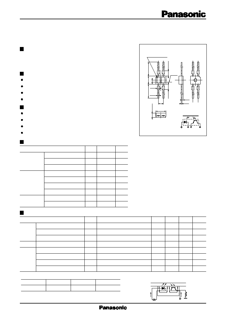
Output current measurement method
2.0
±
0.2
2.0
±
0.2
Mark for indicating
anode side
C0.5
3.4
±
0.3
0.4
2.7
±
0.2
9.0
±
1.0
9.0
±
1.0
Chip
center
1.8
2
4
1
3
4-0.5
±
0.1
4-0.7
0.5
0.15
Pin connection
Unit : mm
1.5
±
0.2
1
4
3
2
,,
,,
,
,,
V
CC
R
L
I
F
I
C
,,
,,,
,,,
,,,
,,,
,,
Evaporated Al
Glass plate
(t = 1mm)
Absolute Maximum Ratings
(Ta = 25∞C)
Parameter
Symbol Ratings
Unit
Input (Light
Reverse voltage (DC)
V
R
3
V
emitting diode)
Forward current (DC)
I
F
50
mA
Power dissipation
P
D
*1
75
mW
Collector current
I
C
20
mA
Output (Photo Collector to emitter voltage
V
CEO
30
V
transistor)
Emitter to collector voltage
V
ECO
5
V
Collector power dissipation
P
C
*2
50
mW
Temperature
Operating ambient temperature
T
opr
≠25 to +85
∞C
Storage temperature
T
stg
≠30 to +100
∞C
Electrical Characteristics
(Ta = 25∞C)
Paramwter
Symbol
Conditions
min
typ
max
Unit
Input
Forward voltage (DC)
V
F
I
F
= 50mA
1.3
1.5
V
characteristics
Reverse current (DC)
I
R
V
R
= 3V
0.01
10
µ
A
Capacitance between terminals
C
t
V
R
= 0V, f
= 1MHz
30
pF
Output characteristics Collector cutoff current
I
CEO
V
CE
= 10V
200
nA
Collector current
I
C
*1, *2
V
CC
= 5V, I
F
= 10mA, R
L
= 100
, d
= 1mm
90
880
µ
A
Transfer
Leakage current
I
D
V
CC
= 5V, I
F
= 10mA, R
L
= 100
200
nA
characteristics Response time
t
r
*3
, t
f
*4
V
CC
= 5V, I
C
= 0.1mA, R
L
= 100
20
µ
s
Collector to emitter saturation voltage V
CE(sat)
I
F
= 20mA, I
C
= 0.1mA
0.4
V
CNB1302
Reflective Photosensor
Overview
CNB1302 is a small, thin reflective photosensor consisting of a
high efficiency GaAs infrared light emitting diode which is integrated
with a high sensitivity Si phototransistor in a single resin package.
Applications
Control of motor and other rotary units
Detection of position and edge
Detection of paper, film and cloth
Start, end mark detection of magnetic tape
*3
Time required for the output current to increase from 10% to 90% of its final value
*4
Time required for the output current to decrease from 90% to 10% of its initial value
*1
I
C
classifications
Class
Q
R
S
I
C
(
µ
A)
90 to 220
180 to 440
360 to 880

2
CNB1302
Reflective Photosensors (Photo Reflectors)
60
50
40
30
20
10
Ambient temperature Ta (∞C )
0
20
40
60
80
100
0
≠ 25
I
F
-- V
F
60
30
20
10
50
40
Forward voltage V
F
(V)
Forward current I
F
(mA)
0.4
0.8
1.2
1.6
2.4
2.0
0
0
Ta = 25∞C
V
F
-- Ta
1.6
1.2
0.8
0.4
Ambient temperature Ta (∞C )
Forward voltage V
F
(V)
0
20
40
60
80
100
0
≠ 40 ≠ 20
0
20
40
60
80
100
≠ 40 ≠ 20
0
20
40
60
80
100
≠ 40 ≠ 20
I
C
-- I
F
Forward current I
F
(mA)
Collector current I
C
(
µ
A)
800
400
200
600
8
16
24
0
0
V
CE
= 5V
Ta = 25∞C
R
L
= 100
d = 1mm
I
C
-- V
CE
Collector to emitter voltage V
CE
(V)
Collector current I
C
(
µ
A)
600
400
300
200
100
500
4
6
8
0
0
d = 1mm
Ta = 25∞C
2
Relative output current I
C
(%)
I
C
-- Ta
160
120
80
40
Ambient temperature Ta (∞C )
0
V
CC
= 5V
I
F
= 10mA
R
L
= 100
I
CEO
-- Ta
10
10
≠2
1
10
≠3
10
≠1
Ambient temperature Ta (∞C )
V
CE
= 10V
Dark current I
CEO
(
µ
A)
10
≠4
1
10
10
≠1
t
r
, t
f
-- I
C
1
Collector current I
C
(mA)
Rise time , fall time t
r
, t
f
(
µ
s)
10
≠1
10
≠2
10
3
10
2
10
V
CC
= 5V
Ta = 25∞C
: t
r
: t
f
Distance d (mm)
I
C
-- d
100
60
40
20
80
Relative output current I
C
(%)
2
4
6
10
8
0
0
V
CC
= 5V
Ta = 25∞C
I
F
= 10mA
I
F
, I
C
-- Ta
Forward current, collector current I
F
, I
C
(mA)
R
L
= 2k
1k
100
15mA
10mA
8mA
6mA
4mA
2mA
I
F
= 20mA
I
F
I
C
10mA
1mA
I
F
= 50mA
d
,
,,