 | –≠–ª–µ–∫—Ç—Ä–æ–Ω–Ω—ã–π –∫–æ–º–ø–æ–Ω–µ–Ω—Ç: PS4051CSE | –°–∫–∞—á–∞—Ç—å:  PDF PDF  ZIP ZIP |

1
PS8461 02/16/00
12345678901234567890123456789012123456789012345678901234567890121234567890123456789012345678901212345678901234567890123456789012123456789012
PS4051/PS4052/PS4053
17V CMOS Analog Multiplexers/Switches
Features
∑
Low On-resistance: 60
typ, with ±5V Supplies,
Minimizes Distortion
∑
On-Resistance Matching between channels better than 6
∑
Guaranteed Low Leakage Currents: <0.1nA at +25
o
C
∑
Rail-to-Rail Analog Signal Range
∑
Low Distortion: <0.04% (600
)
∑
Low Crosstalk: 90dB @100kHz
∑
TTL/CMOS Compatible (with +5V or ±5V Supplies)
∑
Low Power Consumption.
∑
16-pin Narrow SOIC and QSOP Packages save board area
∑
Pin-compatible upgrades for 74HC4051/4052/4053
Applications
∑
Audio and Video Switching and Routing
∑
Lab and Medical Instrumentation
∑
Low-Voltage Data-Acquisition and Process
Control Systems
∑
Battery-Powered Communication Systems
Description
The PS4051/PS4052/PS4053 are precision low-voltage CMOS
analog multiplexers/switches.
The PS4051 is an eight-channel single-ended mux designed to
select one of eight inputs to a common output. What input is
selected depends on the status of three address bits (ADDA-ADDC).
The PS4052 is a differential four-channel mux, controlled by two
address bits: ADDA, and ADDB. The PS4053 is a triple 2-to-1
mux (or triple SPDT, single-pole double-throw, switch).
The INH (inhibit) pin can be driven high, to open all switches
regardless of address bit status. All control inputs are TTL
compatible when V+ = +5V.
These devices are designed to operate with power supplies
from ±2.7V to ±8V. Single-supply operation is possible from
+2.7V to +16V.
When on, each switch conducts current equally well in either
direction and can handle rail-to-rail analog signals. In the
off -state each switch blocks voltages up to the power-supply rails.
Off-leakage current is guaranteed to be less than 0.1nA at +25
o
C,
and < 2.5nA at +85
o
C.
These devices are available in 16-pin DIP, Narrow SOIC, and QSOP
packages for operation over the 40
o
C to +85
o
C temperature range.
Functional Block Diagrams and Pin Configurations
Top Views
For free samples and the latest literature: www.pericom.com, or phone 1-800-435-2336
10
11
12
13
14
15
16
9
7
6
5
4
3
2
1
8
NO1
NO3
COM
NO7
INH
NO5
V-
GND
V+
NO2
NO4
NO0
ADDC
NO6
ADDB
ADDA
LOGIC
10
11
12
13
14
15
16
9
7
6
5
4
3
2
1
8
NO0B
NO1B
COMB
NO3B
INH
NO2B
V-
GND
V+
NO1A
NO2A
COMA
NO3A
NO0A
ADDB
ADDA
LOGIC
10
11
12
13
14
15
16
9
7
6
5
4
3
2
1
8
N0B
NCB
NOA
COMA
INH
NCA
V-
GND
V+
COMB
COMC
NOC
ADDC
NCC
ADDB
ADDA
LOGIC
PS4051
PS4052
PS4053

2
PS8461 02/16/00
12345678901234567890123456789012123456789012345678901234567890121234567890123456789012345678901212345678901234567890123456789012123456789012
PS4051/PS4052/PS4053
17V CMOS Analog Multiplexers/Switches
Caution: Stresses beyond those listed under Absolute Maximum Ratings may cause permanent damage to the device. This is a stress only rating
and operation of the device at these or any other conditions beyond those indicated in the operational sections of this specification is not implied.
Thermal Information
Continuous Power Dissipation
Plastic DIP (derate 10.5mW/
∞
C above +70
∞
C) .............. 800mW
Narrow SO and QSOP
(derate 8.7mW/
∞
C above +70
∞
C) .................................... 650mW
Storage Temperature ........................................ -65
∞
C to +150
∞
C
Lead Temperature (soldering, 10s) ................................. +300
∞
C
Note 1:
Signals on NO, COM, or logic inputs exceeding V+ or V are
clamped by internal diodes. Limit forward diode current to 30mA.
Absolute Maximum Ratings
Voltages Referenced to V
V+ ..................................................................... 0.3V to + 17V
GND ................................................................. 0.3V to + 17V
GND ......................................................... -0.3V to (V+) + 0.3V
V
IN
, V
COM
, V
NO
(1) ..........................................
(V-) 2V to (V+) + 2V
or 30mA, whichever occurs first
Current (any terminal ) ..................................................... 30mA
Peak Current, COM, NO, NC
(pulsed at 1ms, 10% duty cycle) ..................................... 100mA
ESD per method 3015.7 ............................................... >2000V
1
5
0
4
S
P
H
N
I
C
D
D
A
B
D
D
A
A
D
D
A
h
c
t
i
w
S
n
O
1
X
X
X
e
n
o
N
0
0
0
0
0
O
N
0
0
0
1
1
O
N
0
0
1
0
2
O
N
0
0
1
1
3
O
N
0
1
0
0
4
O
N
0
1
0
1
5
O
N
0
1
1
0
6
O
N
0
1
1
1
7
O
N
2
5
0
4
S
P
H
N
I
B
D
D
A
A
D
D
A
h
c
ti
w
S
n
O
1
X
X
e
n
o
N
0
0
0
B
,
A
0
O
N
0
0
1
B
,
A
1
O
N
0
1
0
B
,
A
2
O
N
0
1
1
B
,
A
3
O
N
Truth Tables
3
5
0
4
S
P
H
N
I
C
D
D
A
B
D
D
A
A
D
D
A
s
e
h
c
ti
w
S
n
O
1
X
X
X
e
n
o
N
0
0
0
0
C
O
N
B
O
N
A
O
N
0
0
0
1
C
O
N
B
O
N
A
C
N
0
0
1
0
C
O
N
B
C
N
A
O
N
0
0
1
1
C
O
N
B
C
N
A
C
N
0
1
0
0
C
C
N
B
O
N
A
O
N
0
1
0
1
C
C
N
B
O
N
A
C
N
0
1
1
0
C
C
N
B
C
N
A
O
N
0
1
1
1
C
C
N
B
C
N
A
C
N
Logic 0, V
AL
0.8V
Logic 1, V
IH
2.4V
3
12345678901234567890123456789012123456789012345678901234567890121234567890123456789012345678901212345678901234567890123456789012123456789012
12345678901234567890123456789012123456789012345678901234567890121234567890123456789012345678901212345678901234567890123456789012123456789012
PS4051/PS4052/PS4053
17V CMOS Analog Multiplexers/Switches
PS8461 02/16/00
Electrical Specifications - Dual Supplies
(V± = ± 5V ±10%, GND = 0V, V
AH
= V
IH
= 2.4V, V
AL
= V
IL
= 0.8V)
r
e
t
e
m
a
r
a
P
l
o
b
m
y
S
s
n
o
it
i
d
n
o
C
)
C
∞
(.
p
m
e
T
n
i
M
)
2
(
p
y
T
)
1
(
x
a
M
)
2
(
s
ti
n
U
h
c
ti
w
S
g
o
l
a
n
A
l
a
n
g
i
S
g
o
l
a
n
A
e
g
n
a
R
)
3
(
V
G
O
L
A
N
A
ll
u
F
V
+
V
V
e
c
n
a
t
si
s
e
R
n
O
R
N
O
,
V
5
=
V
,
V
5
=
+
V
V
M
O
C
,
V
3
±
=
I
O
N
A
m
1
=
5
2
0
6
0
0
1
ll
u
F
5
2
1
e
c
n
a
t
si
s
e
R
-
n
O
n
e
e
w
t
e
B
h
c
t
a
M
sl
e
n
n
a
h
C
)
4
(
R
N
O
V
M
O
C
V
r
o
C
N
,
V
3
±
=
I
O
N
,
A
m
1
=
V
5
=
V
,
V
5
=
+
V
5
2
2
1
ll
u
F
8
1
e
c
n
a
t
si
s
e
R
-
n
O
s
s
e
n
t
al
F
)
5
(
R
)
N
O
(
T
A
L
F
,
V
5
=
V
,
V
5
=
+
V
I
O
N
,
A
m
1
=
V
M
O
C
V
0
,
V
3
±
=
5
2
0
1
ll
u
F
5
1
ff
O
O
N
t
n
e
rr
u
C
e
g
a
k
a
e
L
)
6
(
I
O
N
)
F
F
O
(
,
V
5
.
5
=
V
,
V
5
.
5
=
+
V
V
M
O
C
,
V
5
.
4
±
=
V
O
N
V
5
.
4
+
=
5
2
1
.
0
0
5
A
n
ll
u
F
0
.
1
0
0
1
e
g
a
k
a
e
L
ff
O
-
M
O
C
t
n
e
rr
u
C
)
6
(
I
M
O
C
)
F
F
O
(
,
V
5
.
5
=
+
V
V
,
V
5
.
5
=
V
M
O
C
,
V
5
.
4
±
=
V
O
N
V
5
.
4
+
=
1
5
0
4
S
P
5
2
1
.
0
0
5
ll
u
F
5
.
2
0
0
1
2
5
0
4
S
P
3
5
0
4
S
P
5
2
1
.
0
0
5
ll
u
F
5
.
1
0
0
1
e
g
a
k
a
e
L
n
O
M
O
C
)
7
(t
n
e
rr
u
C
I
)
N
O
(
M
O
C
V
M
O
C
V
5
.
4
+
=
1
5
0
4
S
P
5
2
1
.
0
0
5
ll
u
F
5
0
0
1
2
5
0
4
S
P
3
5
0
4
S
P
5
2
1
.
0
0
5
ll
u
F
5
.
2
0
0
1
t
u
p
n
I
c
i
g
o
L
h
g
i
H
ci
g
o
L
e
g
a
tl
o
V
t
u
p
n
I
V
H
A
, V
H
I
ll
u
F
4
.
2
V
w
o
L
ci
g
o
L
e
g
a
tl
o
V
t
u
p
n
I
V
L
A
V
,
L
I
8
.
0
t
n
e
rr
u
C
t
u
p
n
I
e
g
a
tl
o
V
t
u
p
n
I
h
ti
w
w
o
L
r
o
h
g
i
H
I
H
I
I
,
L
I
V
A
V
=
I
V
0
,
+
V
=
1
.
0
-
1
.
0
µ
A
4
PS8461 02/16/00
12345678901234567890123456789012123456789012345678901234567890121234567890123456789012345678901212345678901234567890123456789012123456789012
PS4051/PS4052/PS4053
17V CMOS Analog Multiplexers/Switches
Notes:
1. The algebraic convention, where most negative value is a minimum and most positive is a maximum, is used in this data sheet.
2. Typical values are for DESIGN AID ONLY, not guaranteed or subject to production testing.
3. Guaranteed by design
4.
R
=
R
max
- R
min
5. Flatness is defined as the difference between the maximum and minimum values of on-resistance measured over the specific
analog signal range, i.e., V
NO
= 3V to 0 and 0V to ≠3V.
6. Leakage parameters are 100% tested at maximum rated hot temperature and guaranteed by correlation at +25∫C.
7. Off Isolation = 20log
10
V
COM
/ V
NO
. See Figure 5.
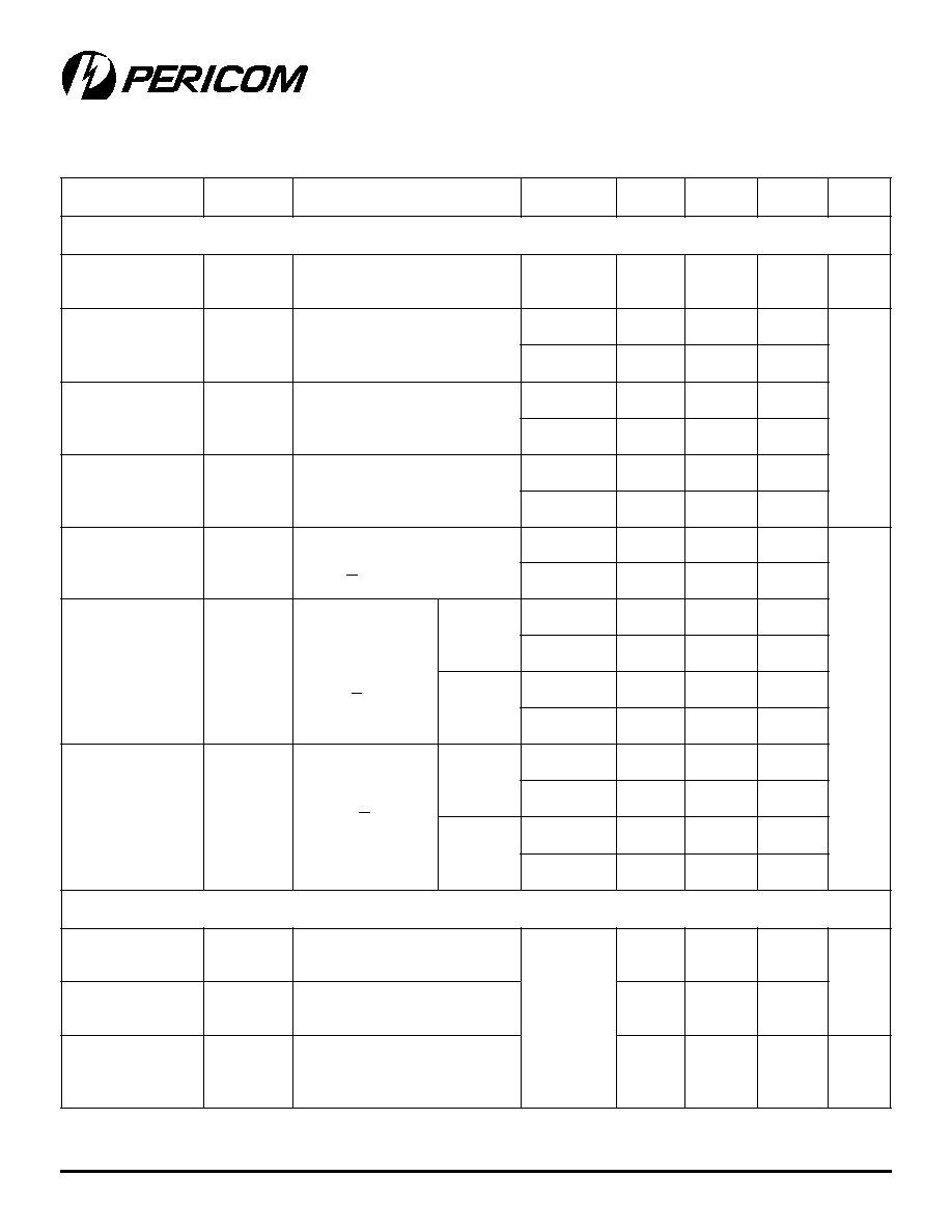
Electrical Specifications - Dual Supplies (continued)
(V± = ±5V ±10%, GND = 0V, V
AH
= V
IH
= 2.4V, V
AL
= V
IL
= 0.8V)
r
e
t
e
m
a
r
a
P
l
o
b
m
y
S
s
n
o
it
i
d
n
o
C
)
C
∞
(
p
m
e
T
n
i
M
)
1
(
p
y
T
)
2
(
x
a
M
)
1
(
s
ti
n
U
c
i
m
a
n
y
D
e
m
i
T
n
o
it
i
s
n
a
r
T
t
S
N
A
R
T
1
e
r
u
g
i
F
5
2
5
7
0
5
2
s
n
e
k
a
M
-
e
r
o
f
e
B
-
k
a
e
r
B
y
al
e
D
e
m
i
T
t
N
E
P
O
3
e
r
u
g
i
F
2
0
1
e
m
i
T
n
O
-
n
r
u
T
t
N
O
2
e
r
u
g
i
F
0
5
5
7
1
ll
u
F
5
2
2
e
m
i
T
ff
O
-
n
r
u
T
t
F
F
O
2
e
r
u
g
i
F
5
2
0
4
0
5
1
ll
u
F
0
0
2
n
o
it
c
e
j
n
I
e
g
r
a
h
C
)
3
(
Q
C
L
,
F
n
1
=
V
S
R
,
V
0
=
S
0
=
,
5
2
2
0
1
C
p
n
o
it
al
o
s
I
ff
O
)
7
(
R
R
I
O
C
L
V
,
F
p
5
1
=
H
N
I
R
,
V
5
=
L
0
5
=
,
V
,z
H
k
0
0
1
=
f
O
N
V
1
=
S
M
R
0
9
B
d
k
l
a
t
s
s
o
r
C
X
K
L
A
T
C
L
R
,
F
p
5
1
=
L
0
5
=
,
,z
H
k
0
0
1
=
f
V
,
6
e
r
u
g
i
F
O
N
V
1
=
S
M
R
2
9
t
u
p
n
I
ci
g
o
L
e
c
n
a
ti
c
a
p
a
C
C
N
I
z
H
M
1
=
f
8
F
p
e
c
n
a
ti
c
a
p
a
C
ff
O
O
N
C
)
F
F
O
(
O
N
V
,z
H
M
1
=
f
O
N
V
0
=
2
ff
O
M
O
C
e
c
n
a
ti
c
a
p
a
C
C
)
F
F
O
(
M
O
C
V
,z
H
M
1
=
f
M
O
C
V
0
=
1
5
0
4
S
P
2
2
5
0
4
S
P
3
5
0
4
S
P
2
n
O
M
O
C
e
c
n
a
ti
c
a
p
a
C
C
)
N
O
(
M
O
C
V
,z
H
M
1
=
f
M
O
C
V
0
=
1
5
0
4
S
P
8
2
5
0
4
S
P
3
5
0
4
S
P
8
y
l
p
p
u
S
e
g
n
a
R
y
l
p
p
u
S
-r
e
w
o
P
ll
u
F
7
.
2
±
8
±
V
t
n
e
rr
u
C
y
l
p
p
u
S
e
v
it
i
s
o
P
+
I
V
H
N
I
V
=
A
,
+
V
r
o
V
0
=
V
5
.
5
=
V
,
V
5
.
5
=
+
V
0
1
µ
A
y
l
p
p
u
S
e
v
it
a
g
e
N
t
n
e
rr
u
C
I
0
1

5
12345678901234567890123456789012123456789012345678901234567890121234567890123456789012345678901212345678901234567890123456789012123456789012
12345678901234567890123456789012123456789012345678901234567890121234567890123456789012345678901212345678901234567890123456789012123456789012
PS4051/PS4052/PS4053
17V CMOS Analog Multiplexers/Switches
PS8461 02/16/00
r
e
t
e
m
a
r
a
P
l
o
b
m
y
S
s
n
o
it
i
d
n
o
C
)
C
∞
(
p
m
e
T
n
i
M
)
1
(
p
y
T
)
2
(
x
a
M
)
1
(
s
ti
n
U
h
c
ti
w
S
e
g
n
a
R
l
a
n
g
i
S
g
o
l
a
n
A
)
3
(
V
G
O
L
A
N
A
ll
u
F
0
+
V
V
e
c
n
a
t
si
s
e
R
n
O
R
N
O
I
O
N
,
A
m
1
=
V
M
O
C
,
V
5
.
3
=
V
5
.
4
=
+
V
5
2
5
2
1
5
2
2
ll
u
F
0
8
2
e
g
a
k
a
e
L
ff
O
-
O
N
t
n
e
rr
u
C
)
8
(
I
)
F
F
O
(
O
N
V
O
N
,
V
0
=
V
M
O
C
V
5
.
5
=
+
V
,
V
5
.
4
=
5
2
1
.
0
0
5
n
ll
u
F
0
1
0
0
1
e
g
a
k
a
e
L
ff
O
-
M
O
C
t
n
e
rr
u
C
)
8
(
I
)
F
F
O
(
M
O
C
,
V
5
.
5
=
+
V
V
M
O
C
,
V
5
.
4
=
V
O
N
r
o
,
V
0
=
V
M
O
C
,
V
0
=
V
O
N
V
5
.
4
=
1
5
0
4
S
P
5
2
1
0
5
ll
u
F
0
1
0
0
1
2
5
0
4
S
P
3
5
0
4
S
P
5
2
1
0
5
ll
u
F
5
0
0
1
e
g
a
k
a
e
L
n
O
-
M
O
C
t
n
e
rr
u
C
)
8
(
I
)
N
O
(
M
O
C
V
M
O
C
V
=
O
N
,
V
5
.
4
=
V
5
.
5
=
+
V
1
5
0
4
S
P
5
2
1
0
5
ll
u
F
0
1
0
0
1
2
5
0
4
S
P
3
5
0
4
S
P
5
2
1
0
5
ll
u
F
0
1
0
0
1
t
u
p
n
I
c
i
g
o
L
l
a
ti
g
i
D
e
g
a
tl
o
V
t
u
p
n
I
h
g
i
H
ci
g
o
L
V
H
A
V
,
H
I
ll
u
F
4
.
2
V
e
g
a
tl
o
V
t
u
p
n
I
w
o
L
ci
g
o
L
V
L
A
V
,
L
I
8
.
0
t
u
p
n
I
h
ti
w
t
n
e
rr
u
C
t
u
p
n
I
w
o
L
r
o
h
g
i
H
e
g
a
tl
o
V
I
H
I
I
,
L
I
V
A
V
=
I
V
0
,
+
V
=
1
1
µ
A
y
l
p
p
u
S
t
n
e
rr
u
C
y
l
p
p
u
S
-
e
v
it
i
s
o
P
+
I
V
A
V
=
I
+
V
r
o
V
0
=
5
2
0
.
1
0
.
1
µ
A
ll
u
F
0
1
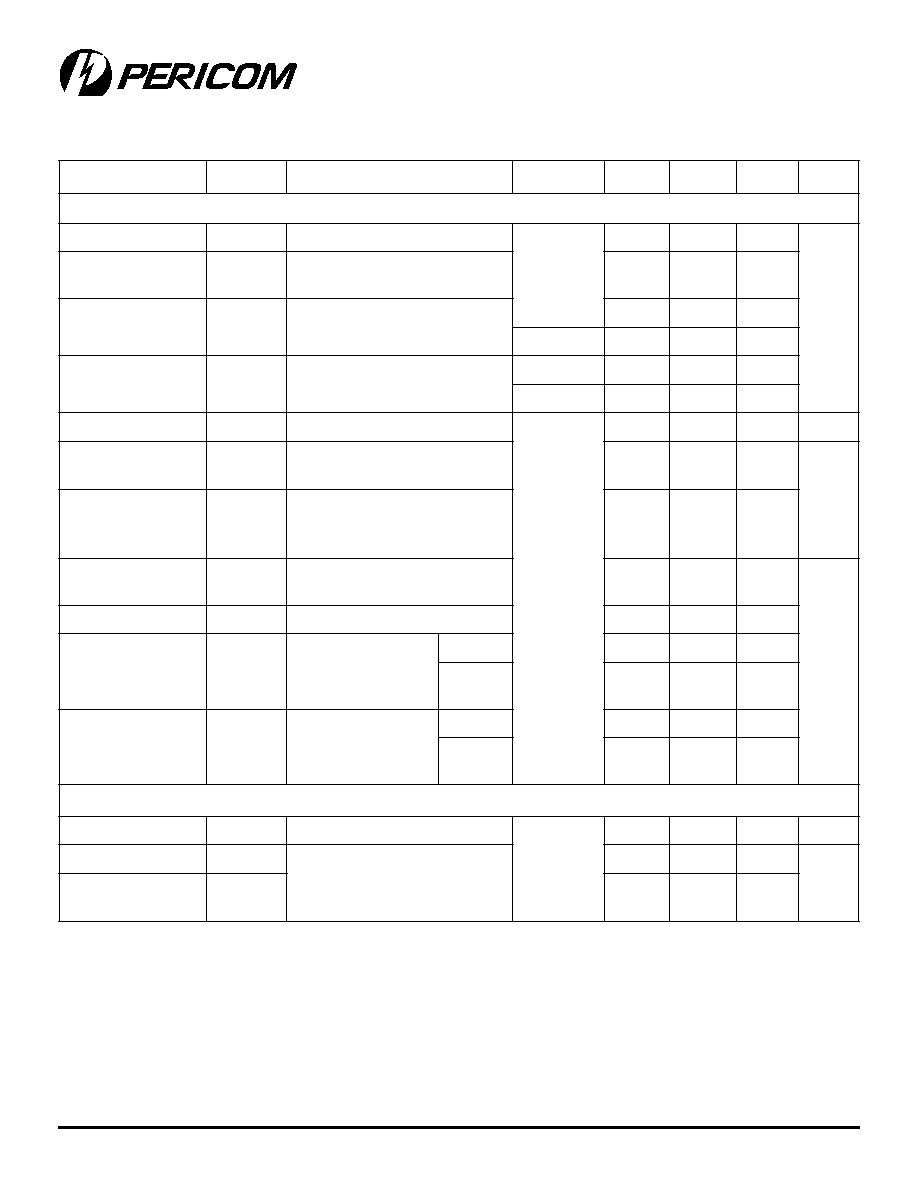
Electrical Characteristics - Single 5V Supply
(V+ = +5V ±10%, V≠ = 0V, GND = 0V, V
AH
= V
IH
= 2.4V, V
AL
= V
IL
= 0.8V)

6
PS8461 02/16/00
12345678901234567890123456789012123456789012345678901234567890121234567890123456789012345678901212345678901234567890123456789012123456789012
PS4051/PS4052/PS4053
17V CMOS Analog Multiplexers/Switches
r
e
t
e
m
a
r
a
P
l
o
b
m
y
S
s
n
o
it
i
d
n
o
C
)
C
∞
(
p
m
e
T
n
i
M
)
1
(
p
y
T
)
2
(
x
a
M
)
1
(
s
ti
n
U
c
i
m
a
n
y
D
e
m
i
T
n
O
-
n
r
u
T
t
N
O
5
2
0
9
0
0
2
s
n
ll
u
F
5
7
2
e
m
i
T
ff
O
-
n
r
u
T
t
F
F
O
5
2
0
6
5
2
1
ll
u
F
5
7
1
e
k
a
M
-
e
r
o
f
e
B
-
k
a
e
r
B
l
a
v
r
e
t
n
I
t
N
E
P
O
5
2
0
3
n
o
it
c
e
j
n
I
e
g
r
a
h
C
)
3
(
Q
C
L
V
,
F
n
1
=
S
R
,
V
0
=
S
=
0
5
.
1
5
C
p
Electrical Characteristics - Single 5V(continued)
(V+ = +5V ±10%, V≠ = 0V, GND = 0V, V
AH
= V
IH
= 2.4V, V
AL
= V
IL
= 0.8V)
r
e
t
e
m
a
r
a
P
l
o
b
m
y
S
s
n
o
it
i
d
n
o
C
)
C
∞
(
p
m
e
T
n
i
M
)
1
(
p
y
T
)
2
(
x
a
M
)
1
(
s
ti
n
U
h
c
ti
w
S
e
g
n
a
R
l
a
n
g
i
S
g
o
l
a
n
A
)
3
(
V
G
O
L
A
N
A
ll
u
F
0
+
V
V
e
c
n
a
t
si
s
e
R
-
n
O
R
N
O
I
O
N
V
,
A
m
1
=
M
O
C
,
V
5
.
1
=
V
3
=
+
V
5
2
0
5
2
5
2
5
ll
u
F
0
0
7
c
i
m
a
n
y
D
e
m
i
T
n
o
it
i
s
n
a
r
T
)
3
(
t
S
N
A
R
T
V
,
1
e
r
u
g
i
F
N
I
V
4
.
2
=
V
1
O
N
V
,
V
5
.
1
=
8
O
N
V
0
=
5
2
0
3
2
5
7
5
s
n
e
m
i
T
n
O
-
n
r
u
T
)
3
(
t
N
O
V
,
2
e
r
u
g
i
F
H
N
I
V
4
.
2
=
V
L
N
I
V
,
V
0
=
1
O
N
V
5
.
1
=
0
0
2
0
0
5
e
m
i
T
ff
O
-
n
r
u
T
)
3
(
t
F
F
O
V
,
2
e
r
u
g
i
F
H
N
I
V
4
.
2
=
V
L
N
I
V
,
V
0
=
1
O
N
V
5
.
1
=
5
7
0
0
4
n
o
it
c
e
j
n
I
e
g
r
a
h
C
)
3
(
Q
C
L
V
,
F
n
0
1
=
S
R
,
V
0
=
S
0
=
1
5
C
p
Electrical Characteristics - Single 3V Supply
(V+ = +3.3V ±10%, V≠ = 0V, GND = 0V, V
AH
= V
IH
= +2.4V, V
AL
= V
IL
L
= +0.8V)
Notes:
1. The algebraic convention, where the most negative value is a minimum and the most positive is a maximum, is used
in this data sheet.
2.
Typical values are for DESIGN AID ONLY, not guaranteed or subject to production testing.
3. Guaranteed by design
4.
R
=
R
max
- R
min
5. Flatness is defined as the difference between the maximum and minimum value of on-resistance measured.
6. Leakage parameters are 100% tested at maximum rated hot temperature and guaranteed by correlation at +25∫C.
7. Worst-case isolation is on channel 4 because of its proximity to the COM pin. Off isolation = 20log V
COM
/V
NO
,
V
COM
= output, VNO = input to off switch
8. Leakage testing at single supply is guaranteed by testing with dual supplies.
7
12345678901234567890123456789012123456789012345678901234567890121234567890123456789012345678901212345678901234567890123456789012123456789012
12345678901234567890123456789012123456789012345678901234567890121234567890123456789012345678901212345678901234567890123456789012123456789012
PS4051/PS4052/PS4053
17V CMOS Analog Multiplexers/Switches
PS8461 02/16/00
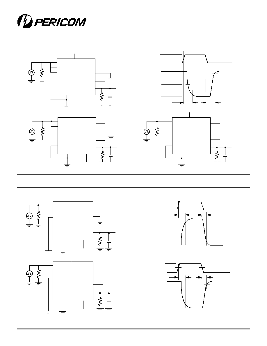
Test Circuits/Timing Diagrams
Figure 1. Transition Time
Figure 2. Switching Times
tr <20ns
tf <20ns
ttrans
VNO7
ON
ttrans
VOUT
VNO0
90%
90%
Logic
Input
Switch
Output
V+
0V
0V
50%
V+
V+
NO7
COM
GND
V-
V+
V-
V-
NO0
ADDC
ADDB
ADDA
INH
NO1-NO6
50
9
V
OUT
300
9
35pF
PS4051
V+
V+
NO3
COM
GND
V-
V+
V-
V-
NO0
ADDB
ADDA
INH
NO1-NO2
50
9
V
OUT
300
9
35pF
PS4052
V+
V+
COM
GND
V-
V-
V+
V-
NO
ADD
INH
NC
50
9
V
OUT
300
9
35pF
PS4053
V+
V+
COM
GND
V-
V+
V-
NO0
ADDX
INH
NOX
50
9
V
OUT
300
9
35pF
tr <20ns
tf <20ns
VOUT
tON
90%
10%
Logic
Input
Switch
Output
V+
0V
0V
50%
PS4051
PS4052
V+
+5V
COM
GND
V-
V+
V-
NO
NC
ADD
INH
50
9
V
OUT
300
9
35pF
V-
PS4053
tOFF
tr <20ns
tf <20ns
VOUT
tON
90%
10%
Logic
Input
Switch
Output
V+
0V
0V
50%
tOFF
V-
8
PS8461 02/16/00
12345678901234567890123456789012123456789012345678901234567890121234567890123456789012345678901212345678901234567890123456789012123456789012
PS4051/PS4052/PS4053
17V CMOS Analog Multiplexers/Switches
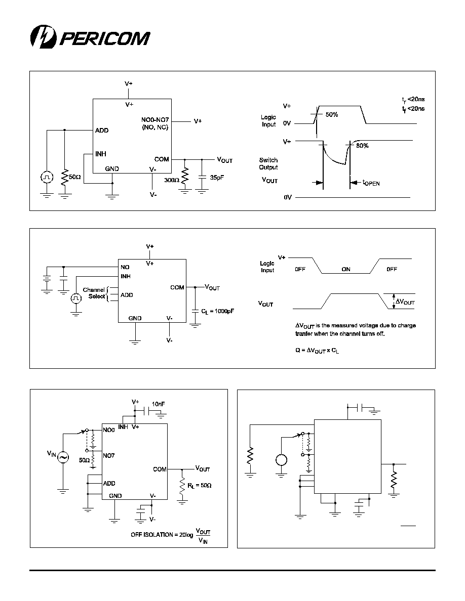
Figure 3. Break-Before-Make Interval
Figure 4. Charge Injection
Figure 5. Off Isolation
Figure 6. Crosstalk
V+
V+
COM
GND
INH
V-
V-
10nF
10nF
NO0
NO1
NO7
ADD
V
OUT
R
L
= 50
9
V
OUT
V
IN
V
IN
R = 1k
9
R
G
= 50
9
CROSSTALK = 20log
~
PS4051
PS4052
50
9

9
12345678901234567890123456789012123456789012345678901234567890121234567890123456789012345678901212345678901234567890123456789012123456789012
12345678901234567890123456789012123456789012345678901234567890121234567890123456789012345678901212345678901234567890123456789012123456789012
PS4051/PS4052/PS4053
17V CMOS Analog Multiplexers/Switches
PS8461 02/16/00
Figure 8. NO/COM Capacitance
Pericom Semiconductor Corporation
2380 Bering Drive ∑ San Jose, CA 95131 ∑ 1-800-435-2336 ∑ Fax (408) 435-1100 ∑ http://www.pericom.com
r
e
b
m
u
N
t
r
a
P
e
r
u
t
a
r
e
p
m
e
T
e
g
a
k
c
a
P
E
P
C
1
5
0
4
S
P
C
∫
0
7
+
o
t
C
∫
0
6
1
-
P
I
D
P
E
S
C
1
5
0
4
S
P
C
∫
0
7
+
o
t
C
∫
0
6
1
-
C
I
O
S
w
o
rr
a
N
E
E
C
1
5
0
4
S
P
C
∫
0
7
+
o
t
C
∫
0
6
1
-
P
O
S
Q
E
P
E
1
5
0
4
S
P
C
∫
5
8
+
o
t
C
∫
0
4
6
1
-
P
I
D
P
E
S
E
1
5
0
4
S
P
C
∫
5
8
+
o
t
C
∫
0
4
6
1
-
C
I
O
S
w
o
rr
a
N
E
E
E
1
5
0
4
S
P
C
∫
5
8
+
o
t
C
∫
0
4
6
1
-
P
O
S
Q
E
P
C
2
5
0
4
S
P
C
∫
0
7
+
o
t
C
∫
0
6
1
-
P
I
D
P
E
S
C
2
5
0
4
S
P
C
∫
0
7
+
o
t
C
∫
0
6
1
-
C
I
O
S
w
o
rr
a
N
E
E
C
2
5
0
4
S
P
C
∫
0
7
+
o
t
C
∫
0
6
1
-
P
O
S
Q
Ordering Information
r
e
b
m
u
N
t
r
a
P
e
r
u
t
a
r
e
p
m
e
T
e
g
a
k
c
a
P
E
P
E
2
5
0
4
S
P
C
∫
5
8
+
o
t
C
∫
0
4
6
1
-
P
I
D
P
E
S
E
2
5
0
4
S
P
C
∫
5
8
+
o
t
C
∫
0
4
6
1
-
C
I
O
S
w
o
rr
a
N
E
E
E
2
5
0
4
S
P
C
∫
5
8
+
o
t
C
∫
0
4
6
1
-
P
O
S
Q
E
P
C
3
5
0
4
S
P
C
∫
0
7
+
o
t
C
∫
0
6
1
-
P
I
D
P
E
S
C
3
5
0
4
S
P
C
∫
0
7
+
o
t
C
∫
0
6
1
-
C
I
O
S
w
o
rr
a
N
E
E
C
3
5
0
4
S
P
C
∫
0
7
+
o
t
C
∫
0
6
1
-
P
O
S
Q
E
P
E
3
5
0
4
S
P
C
∫
5
8
+
o
t
C
∫
0
4
6
1
-
P
I
D
P
E
S
E
3
5
0
4
S
P
C
∫
5
8
+
o
t
C
∫
0
4
6
1
-
C
I
O
S
w
o
rr
a
N
E
E
E
3
5
0
4
S
P
C
∫
5
8
+
o
t
C
∫
0
4
6
1
-
P
O
S
Q