Document Outline
- 1 FEATURES
- 2 APPLICATIONS
- 3 GENERAL DESCRIPTION
- 4 ORDERING INFORMATION
- 5 BLOCK DIAGRAM
- 6 FUNCTIONAL DESCRIPTION
- 7 SOFTWARE DESCRIPTION
- 8 RELATED INFORMATION
- 9 DATA SHEET STATUS
- 10 DEFINITIONS
- 11 DISCLAIMERS

DATA SHEET
Product specification
Supersedes data of 2000 Feb 01
2002 May 23
INTEGRATED CIRCUITS
SLEV900
I-CODE Evaluation kit

2002 May 23
2
Philips Semiconductors
Product specification
I-CODE Evaluation kit
SLEV900
CONTENTS
1
FEATURES
2
APPLICATIONS
3
GENERAL DESCRIPTION
4
ORDERING INFORMATION
5
BLOCK DIAGRAM
6
FUNCTIONAL DESCRIPTION
6.1
Hardware
6.2
Software
6.2.1
System requirements
6.2.2
Contents of disks
6.2.3
Software installation
6.2.4
Restrictions of Windows I-CODE demo
software
7
SOFTWARE DESCRIPTION
7.1
Main screen
7.2
Read serial numbers
7.3
Read
7.4
Write
7.5
Read EAS
7.6
Activate EAS
7.7
Deactivate EAS
7.8
EAS command
7.9
Memory content
8
RELATED INFORMATION
8.1
Additional documents
8.2
Training
8.3
Support hot-line
9
DATA SHEET STATUS
10
DEFINITIONS
11
DISCLAIMERS

2002 May 23
3
Philips Semiconductors
Product specification
I-CODE Evaluation kit
SLEV900
1
FEATURES
The evaluation kit comprises the following components:
∑
I-CODE
(1)
read/write device
∑
I-CODE antenna
∑
Power supply cable 24 V
∑
PC serial interface cable
∑
Ten I-CODE labels respectively inlets
∑
Three disks with:
≠ Demonstration software
≠ Evaluation software
≠ Source code.
∑
I-CODE evaluation kit user manual
∑
Interface protocol reader host description.
2
APPLICATIONS
∑
Easy plug and play demonstration of I-CODE
functionality
∑
Fast implementation of small applications and feasibility
studies.
3
GENERAL DESCRIPTION
The I-CODE evaluation kit offers a tool, which was
designed for two major purposes:
∑
Easy plug and play demonstration of I-CODE
functionality (with the use of the windows demo
software)
∑
Fast implementation of small applications and feasibility
studies (using the interface protocol description and the
C-software library). In addition the attached DOS based
evaluation software offers an easy possibility to evaluate
all commands, within the command set of the I-CODE
label IC. Moreover application specific configurations of
the demo reader may be performed with this software.
Since Philips Semiconductors is mainly focused on the
label IC, Philips does not produce complete inlets or
labels. Nevertheless we have attached labels and inlets of
manufacturers that already incorporated I-CODE in their
standard product range.
For detailed information on the I-CODE1 label IC
functionality encompassing the description of the memory
organisation, the serial number, write access conditions
special functions and family code, please refer to data
sheet
"SL1ICS3001 I-CODE1 Label IC".
(1) I-CODE - is a trademark of Koninklijke Philips Electronics N.V.
4
ORDERING INFORMATION
TYPE NUMBER
NAME
ORDER CODE (12NC)
SLEV900/AFB
I-CODE Evaluation kit
9352 623 26122

2002 May 23
4
Philips Semiconductors
Product specification
I-CODE Evaluation kit
SLEV900
5
BLOCK DIAGRAM
handbook, full pagewidth
MGW407
EXTERNAL
PC
I-CODE READER
SLRM900
I-CODE
ANTENNA
antenna
cable
I-CODE
labels
3 disks
2 manuals
I-CODE
inlets
power supply
cable DC
serial
interface
cable
EXTERNAL
POWER
SUPPLY
Fig.1 Block diagram.
6
FUNCTIONAL DESCRIPTION
6.1
Hardware
Getting started with the I-CODE evaluation kit requires the
following steps:
1. Connect the antenna cable to the BNC connector at
the I-CODE reader
2. Connect the serial interface cable to the COM1 or
COM2 port at your host PC and to the connector at the
I-CODE reader
3. Connect the 24 V power supply cable to the
appropriate connector at the I-CODE reader and to a
24
±
1 V, 40 W power supply
4. Connect the 24 V power supply to the mains and
switch it on.
The I-CODE reader is now ready for use.
Remark: The I-CODE evaluation kit is delivered with an
RF power output of 4 W. Since the evaluation kit antenna
was designed for that output power level, an RF power
higher than 4 W might damage the evaluation kit antenna
If higher RF power is desired a customized antenna has to
be used (e.g. gate antennas).
The RF power output is adjustable by software (e.g. with
CRMTEST3.EXE).
6.2
Software
6.2.1
S
YSTEM REQUIREMENTS
Minimum requirements of external PC:
∑
Pentium 133 MHz; 32 Mb RAM
∑
UART 16 550A (or compatible)
∑
5 Mb free disk space
∑
Floppy disk drive 3.5 inch
∑
Resolution of the video-card and monitor:
≠ 800
◊
600 with small fonts or
≠ 1024
◊
768 with large fonts.
∑
Colour depth:
≠ 16-bit (65536).
2002 May 23
5
Philips Semiconductors
Product specification
I-CODE Evaluation kit
SLEV900
6.2.2
C
ONTENTS OF DISKS
The serial PC library crm_s32.dll is not part of the SLEV900, but is supplied by Philips as a design tool that is free of
charge and without any warranties.
DISK
PROGRAM
DESCRIPTION
Disk 1
SETUP.EXE
installation program of WIN demo ICODE.EXE
Disk 2
SETUP.W02
second part of installation program
Disk 3
DOS_SW3.ZIP
DOS demo CRMTEST3.EXE
VC6SOURCE.ZIP
visual C++ 6.0 source codes of WIN demo ICODE.EXE
6.2.3
S
OFTWARE INSTALLATION
The I-CODE demonstration software works with
Windows 95, Windows 98, and Windows NT 4.0.
Insert disk 1, start the SETUP.EXE program and follow the
instructions.
If you want to change the COM port after the software
installation, open the file ICODE.INI, in the directory where
you have installed the software, with a text editor and
modify the line COM = COMx (x = 1 or 2).
The baud rate of the reader is set to 57.6 kbaud as default.
6.2.4
R
ESTRICTIONS OF
W
INDOWS
I-CODE
DEMO
SOFTWARE
The Windows Demo Software of the I-code Evaluation Kit
does not allow the changing of Block 2 (Write Access
Conditions) and of the QUIET bits in Block 3. The use of
Family Codes and/or Application Identifiers is not
supported.
7
SOFTWARE DESCRIPTION
The demonstration software shows the basic features of
the I-CODE system. To start the program double click the
I-CODE demo icon.
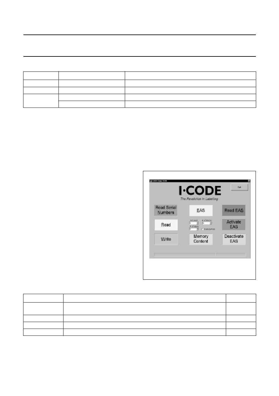
7.1
Main screen
The main screen allows the user to set up some
parameters (see Table 1) and to start all supported
commands; see the buttons in the dialogue box shown in
Fig.2.
Fig.2 Main screen of demonstration software.
Table 1
Parameters in the main screen of the demonstration software
To start a command click the corresponding button in the dialogue box or press the Alt-key and the underlined character.
To exit a command, first click the Stop-button and then the Exit-button.
PARAMETER
DESCRIPTION
EXAMPLE
1st block
first block in the user memory with which you want to start the access; the first
block in the user memory is block 4
4
# of blocks
number of blocks starting with the 1st block you want to access
4
# of labels
maximum number of labels that will be in the antenna field
8
Enable FastMode
if you click at this button the I-CODE reader works in fast mode
2002 May 23
6
Philips Semiconductors
Product specification
I-CODE Evaluation kit
SLEV900
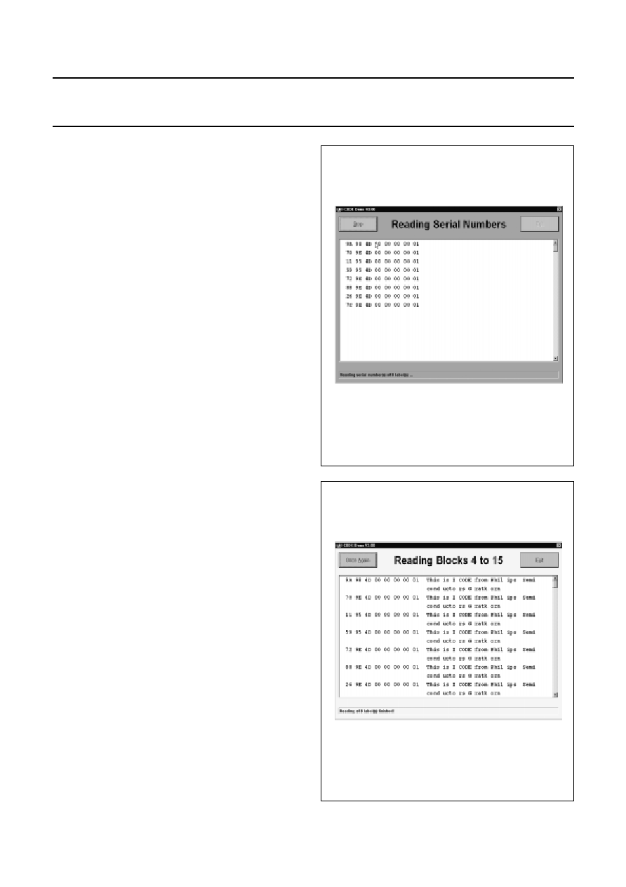
7.2
Read serial numbers
This command reads the unique serial numbers
(2 blocks = 8 bytes, least significant byte first) of the labels
in the antenna field (see Fig.3). Each additional label which
enters the field is added to the list. To clear the list click on
the Stop-button and then the Once again-button.
The status line shows information about the number of
detected labels.
The two arrow buttons on the right side of the screen can
be used (after clicking the Stop-button) to scroll the content
of the screen.
Fig.3 Reading serial numbers of 8 labels.
7.3
Read
After the button Read in the main menu is clicked, Fig.4
appears. With this command you will get the unique serial
numbers and the content of read labels including the user
memory. The first block and the number of blocks depend
on the set-up in the main menu.
Fig.4 Reading blocks 4 of 15.

2002 May 23
7
Philips Semiconductors
Product specification
I-CODE Evaluation kit
SLEV900
7.4
Write
After selecting this command you can input your new data
in the status line (see Fig.5). The length depends on the
selected number of blocks.
Fig.5 Write blocks.
By clicking on the OK-button or pressing the Alt and o keys
together, the selector box will appear (see Fig.6). You can
select none, some or all of previously read labels by
clicking on the corresponding item. Only the labels with
selected serial numbers will be written to with the new data
by clicking the OK-button.
The button Next label and the button Select are displayed
from version 3.02 and further.
Fig.6 I-CODE demo write selection.
2002 May 23
8
Philips Semiconductors
Product specification
I-CODE Evaluation kit
SLEV900
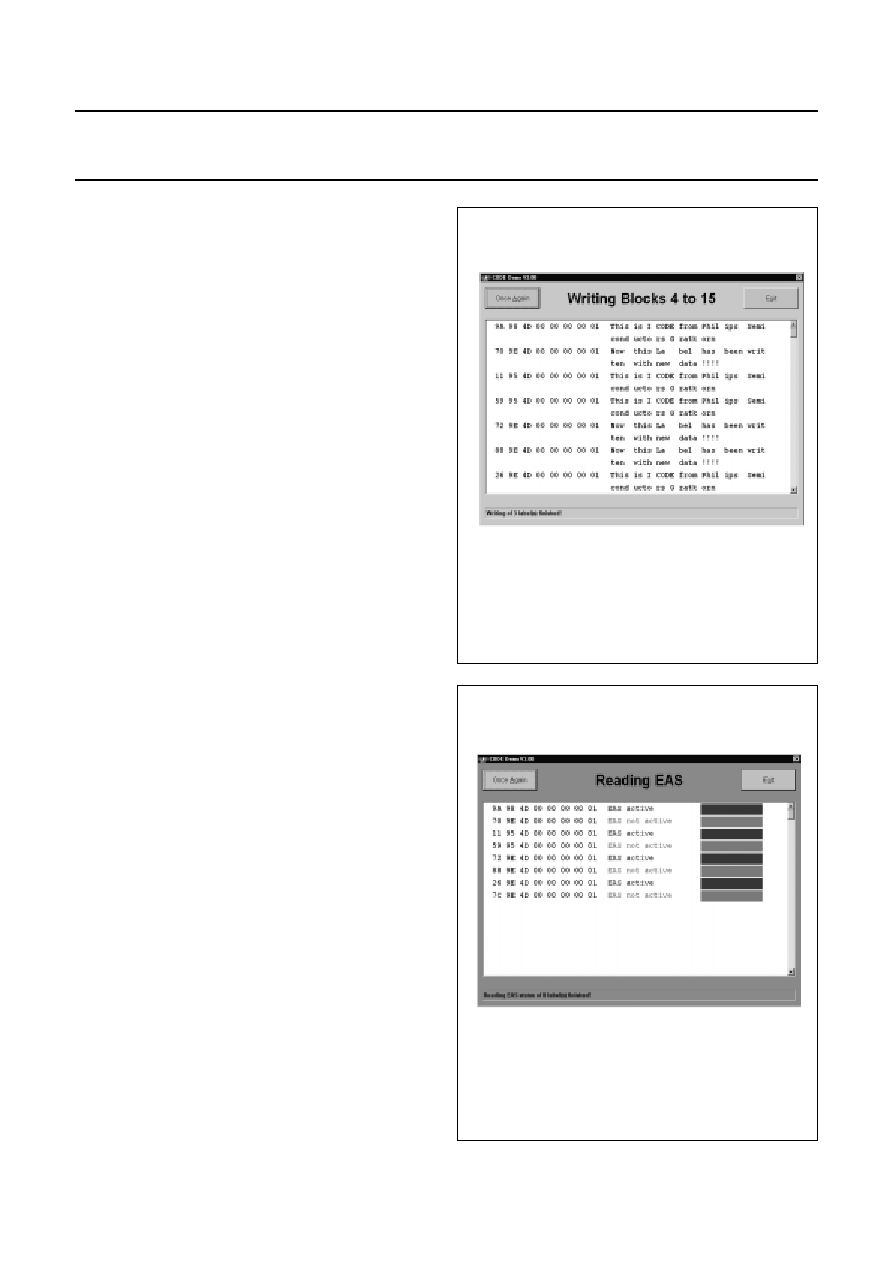
After clicking the OK-button in Fig.6 the screen Fig.7 will
appear.
Fig.7 Writing blocks 4 to 15.
7.5
Read EAS
This command shows the unique serial numbers and the
Electronic Article Surveillance (EAS) status of all the
detected labels (see Fig.8).
Fig.8 Reading EAS.
2002 May 23
9
Philips Semiconductors
Product specification
I-CODE Evaluation kit
SLEV900
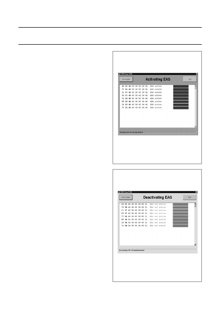
7.6
Activate EAS
This command activates the EAS function of none, some
or all of the previously read labels (see Fig.9). A selector
box as described at the write command is used to select
the concerned labels. The background colour of the serial
numbers in the selector box shows the actual EAS status
of the labels.
Fig.9 Activate EAS.
7.7
Deactivate EAS
This command deactivates the EAS function of none,
some or all of the previously read labels (see Fig.10).
A selector box as described at the write command is used
to select the concerned labels. The background colour of
the serial numbers in the selector box shows the actual
EAS status of the labels.
Fig.10 Deactivate EAS.

2002 May 23
10
Philips Semiconductors
Product specification
I-CODE Evaluation kit
SLEV900
7.8
EAS command
The following screen is shown if the EAS-button is clicked
on the main screen (see Fig.11).
Fig.11 Electronic article surveillance.
The screen (see Fig.12) changes to the following if at least
one label with activated EAS bits is found in the antenna
field.
Fig.12 Electronic article surveillance.
2002 May 23
11
Philips Semiconductors
Product specification
I-CODE Evaluation kit
SLEV900
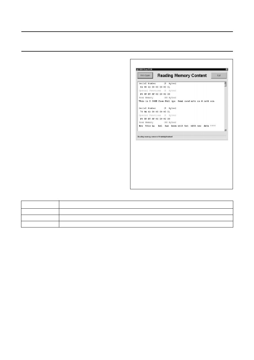
7.9
Memory content
As a result of this command you get the complete memory
content of all detected labels (see Fig.13).
Fig.13 Reading memory content.
Table 2
Memory content
BLOCK NUMBER
CONTENT
0 to 1
unique serial number (8 bytes)
2 to 3
special function blocks for write access and EAS/QUIET (8 bytes)
4 to 15
user memory (48 bytes)
8
RELATED INFORMATION
8.1
Additional documents
Additional information concerning long range antennas
and the functionality of the label IC is available in the
following documents:
∑
Data sheet:
"SL1ICS3001 I-CODE1 Label IC"
∑
Data sheet:
"SL1ICS3001 I-CODE1 Label IC; protocol
air interface"
∑
Application note:
"I-CODE design of Read/Write
antenna".
In order to receive the additional documents, please
contact Philips Semiconductors Gratkorn Austria.
8.2
Training
It is strongly recommend to attend our I-CODE system and
antenna training, which takes place on a regular basis at
Philips Semiconductors Gratkorn Austria. The training
provides background information and example antenna
design, far beyond the information included in the
available documents.
Please contact us for registration and further information.
8.3
Support hot-line
In case of further questions concerning the evaluation kit,
please feel free to contact us on the Internet at URL
http://www.semiconductors.philips.com.

2002 May 23
12
Philips Semiconductors
Product specification
I-CODE Evaluation kit
SLEV900
9
DATA SHEET STATUS
Notes
1. Please consult the most recently issued data sheet before initiating or completing a design.
2. The product status of the device(s) described in this data sheet may have changed since this data sheet was
published. The latest information is available on the Internet at URL http://www.semiconductors.philips.com.
DATA SHEET STATUS
(1)
PRODUCT
STATUS
(2)
DEFINITIONS
Objective data
Development
This data sheet contains data from the objective specification for product
development. Philips Semiconductors reserves the right to change the
specification in any manner without notice.
Preliminary data
Qualification
This data sheet contains data from the preliminary specification.
Supplementary data will be published at a later date. Philips
Semiconductors reserves the right to change the specification without
notice, in order to improve the design and supply the best possible
product.
Product data
Production
This data sheet contains data from the product specification. Philips
Semiconductors reserves the right to make changes at any time in order
to improve the design, manufacturing and supply. Changes will be
communicated according to the Customer Product/Process Change
Notification (CPCN) procedure SNW-SQ-650A.
10 DEFINITIONS
Short-form specification
The data in a short-form
specification is extracted from a full data sheet with the
same type number and title. For detailed information see
the relevant data sheet or data handbook.
Limiting values definition
Limiting values given are in
accordance with the Absolute Maximum Rating System
(IEC 60134). Stress above one or more of the limiting
values may cause permanent damage to the device.
These are stress ratings only and operation of the device
at these or at any other conditions above those given in the
Characteristics sections of the specification is not implied.
Exposure to limiting values for extended periods may
affect device reliability.
Application information
Applications that are
described herein for any of these products are for
illustrative purposes only. Philips Semiconductors make
no representation or warranty that such applications will be
suitable for the specified use without further testing or
modification.
11 DISCLAIMERS
Life support applications
These products are not
designed for use in life support appliances, devices, or
systems where malfunction of these products can
reasonably be expected to result in personal injury. Philips
Semiconductors customers using or selling these products
for use in such applications do so at their own risk and
agree to fully indemnify Philips Semiconductors for any
damages resulting from such application.
Right to make changes
Philips Semiconductors
reserves the right to make changes, without notice, in the
products, including circuits, standard cells, and/or
software, described or contained herein in order to
improve design and/or performance. Philips
Semiconductors assumes no responsibility or liability for
the use of any of these products, conveys no licence or title
under any patent, copyright, or mask work right to these
products, and makes no representations or warranties that
these products are free from patent, copyright, or mask
work right infringement, unless otherwise specified.

2002 May 23
13
Philips Semiconductors
Product specification
I-CODE Evaluation kit
SLEV900
NOTES

2002 May 23
14
Philips Semiconductors
Product specification
I-CODE Evaluation kit
SLEV900
NOTES

2002 May 23
15
Philips Semiconductors
Product specification
I-CODE Evaluation kit
SLEV900
NOTES

© Koninklijke Philips Electronics N.V. 2002
SCA74
All rights are reserved. Reproduction in whole or in part is prohibited without the prior written consent of the copyright owner.
The information presented in this document does not form part of any quotation or contract, is believed to be accurate and reliable and may be changed
without notice. No liability will be accepted by the publisher for any consequence of its use. Publication thereof does not convey nor imply any license
under patent- or other industrial or intellectual property rights.
Philips Semiconductors ≠ a worldwide company
Contact information
For additional information please visit http://www.semiconductors.philips.com.
Fax: +31 40 27 24825
For sales offices addresses send e-mail to: sales.addresses@www.semiconductors.philips.com.
Printed in The Netherlands
613502/02/pp
16
Date of release:
2002 May 23
Document order number:
9397 750 08395