ChipFind - документация

Электронный компонент: TDA5147CH

Скачать:  PDF   ZIP
DATA SHEET
Preliminary specification
File under Integrated Circuits, IC11
1997 Jul 09
INTEGRATED CIRCUITS
TDA5147CH
12 V Voice Coil Motor (VCM) driver
and spindle motor drive
combination chip
1997 Jul 09
2
Philips Semiconductors
Preliminary specification
12 V Voice Coil Motor (VCM) driver and
spindle motor drive combination chip
TDA5147CH
FEATURES
Spindle motor driver
Internal 2 A peak current power drivers
Low R
ds(on)
(1
maximum total) for high, low and
isolation drivers
Induction sense start-up option
External current sense resistor
Soft switching on both upper and lower drivers
Programmable linear or Pulse Width Modulation (PWM)
spindle mode
Provide spindle active dynamic braking mode.
Voice coil motor driver
1.2 A VCM power driver
Maximum of 1 V drop across the power driver at 0.8 A
External current sense resistor, with sense amplifier
External current control loop compensation
15 kHz (typ.) VCM current control loop bandwidth
Three modes of operation:
Enable VCM
Retract
Disable
Brake after park circuitry.
Power monitor and retract circuit
+5 V and +12 V power monitor threshold accuracy
2%
Hysteresis on both power monitor comparators
Internal voltage reference: precision 2%
Buffered reference voltage output pin
Retract circuit operates down to 2 V
Internal thermal sense circuitry with an over temperature
shut down option
Internal boost voltage generator
Sleep mode.
Thermal warning circuit
Output active 15
C before general thermal shutdown.
APPLICATIONS
Hard disk drive for Personal Computer products.
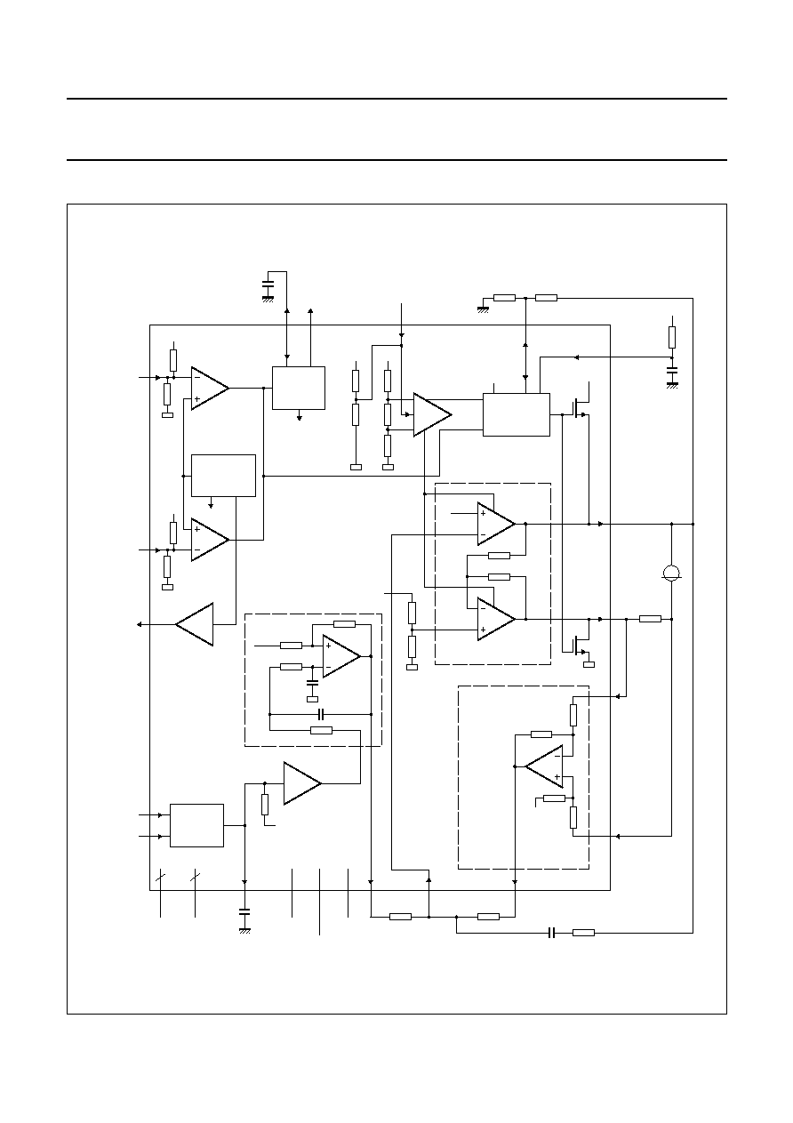
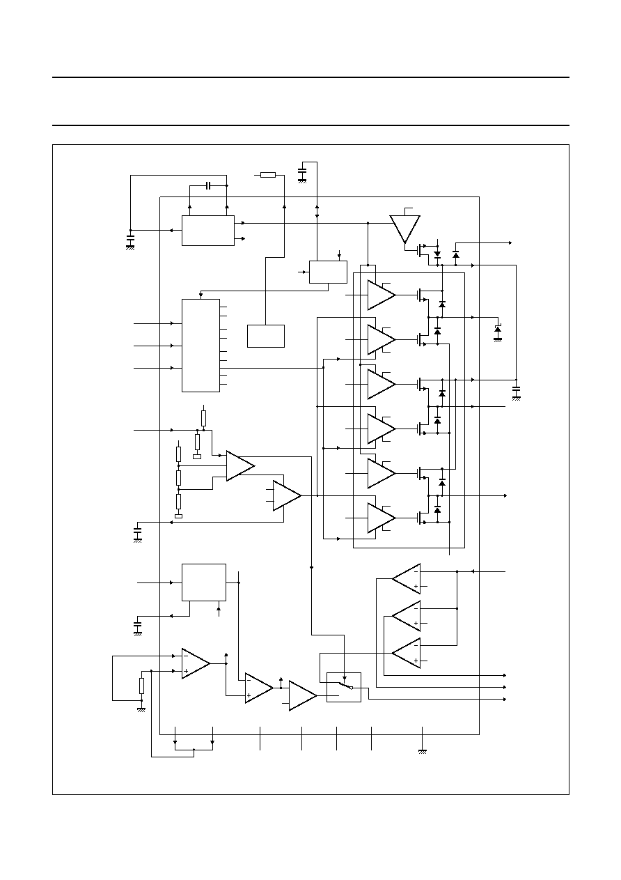
GENERAL DESCRIPTION
The TDA5147CH is an ASIC combination chip that
includes the following functions:
spindle motor driver
voice coil motor driver
retract
Power-on.
The circuit is contained in a 64-pin QFP package.
The TDA5147CH is controlled by a custom digital ASIC
(see Chapter "Application Information"). The custom ASIC
provides the necessary commutation sequences for the
spindle drivers via the SCNTL1, SCNTL2 and SCNTL3
inputs. Spindle speed is monitored by comparator outputs
SENU, SENV and SENWIS. Motor speed control is
accomplished by a PWM signal (input at pin SIPWM).
Control of the VCM circuits is via the V
IPWMH
and V
IPWML
input signals. These inputs provide control of the voice coil
current.
ORDERING INFORMATION
TYPE
NUMBER
PACKAGE
NAME
DESCRIPTION
VERSION
TDA5147CH
QFP64
plastic quad flat package; 64 leads (lead length 1.6 mm);
body 14
14
2.7 mm
SOT393-1
1997 Jul 09
3
Philips Semiconductors
Preliminary specification
12 V Voice Coil Motor (VCM) driver and
spindle motor drive combination chip
TDA5147CH
QUICK REFERENCE DATA
SYMBOL
PARAMETER
MIN.
TYP.
MAX.
UNIT
Supply voltage
V
CC5
analog supply voltage 1
4.5
5.0
5.5
V
V
CCA12
analog supply voltage 2
10.8
12
13.2
V
V
CCS12
power supply for spindle motor drivers
10.8
12
13.2
V
V
CC1V12
power supply 1 for VCM driver
10.8
12
13.2
V
V
CC2V12
power supply 2 for VCM driver
10.8
12
13.2
V
Drivers
I
spin(max)
maximum spindle current
-
2
-
A
I
VCM(max)
maximum VCM current
-
1.2
-
A
1997 Jul 09
4
Philips Semiconductors
Preliminary specification
12 V Voice Coil Motor (VCM) driver and
spindle motor drive combination chip
TDA5147CH
BLOCK DIAGRAMS
Fig.1 Block diagram of voice coil motor driver.
handbook, full pagewidth
MGG845
VDD
VDD
autopark
park
disable
PARK
CIRCUITRY
Vrefout
POWER AMPLIFIERS
59
53
51
VCMP
Rs
60
VISENL
SENSE
Vrefout
57
VISENH
61
47
4
VCMINP
VFLTOUT
VISENS1
VCMN
50
VPCNTL
SHPWR1
RETADJ
35
Vrefout
Vrefout
3
64
49
9
6, 7
54, 55, 56
VFLTINP
VCC1V12
VCC2V12
VCC5
UNDER
VOLTAGE
GENERATOR
PWM
DECODER
POR
DETECTOR
to spindle
section
1
GNDSUBB GNDV
2
16
17
VCC5
Vref
52
VCCA12
PORN
CPOR
14
TDA5147CH
15
POR12VADJ
POR5VADJ
Vrefout
VIPWML
VIPWMH
VCCA12
SHPWR2,3
SHPWRZ
BRKTC
M
1997 Jul 09
5
Philips Semiconductors
Preliminary specification
12 V Voice Coil Motor (VCM) driver and
spindle motor drive combination chip
TDA5147CH
handbook, full pagewidth
VCC5
VCC5
disable
disable
brake
DRIVER
DRIVER
from PORN block
VCCS12
disable
disable
brake
DRIVER
DRIVER
40
39
5
28
23
disable
disable
brake
DRIVER
DRIVER
10
W.L
W.H
V.L
V.H
U.L
U.H
control
amplifier
PWM/LIN
Iset
Isense
COMP
VCC5
LOGIC
DECODER
U.H
U.L
V.H
V.L
W.H
W.L
brake
disable
THERMAL
SWITCH
PWM
UPPER
BOOSTER
29
41
30
BSTCP2
BSTCP1
BSTFLT
24
58
SPWMTC
PWM/LIN
TEMP
lcompare
to the VCM
output
stages
20
SCNTL1
21
22
SCNTL2
SCNTL3
13
SMODE1
37
SCOMP
SISINK1, SISINK2
COMP
SDRVU
25
SHPWR1
SDRVU
SHPWR2
SHPWR3
Cclamp
SDRVV
SDRVW
SDRVN
COMP
SDRVV
COMP
SDRVW
27
SENV
26
SENU
18
SENWIS
multiplexer
COMP
Isense
AMP
SISENL 46
SISENH 45
Rsense
36
VCCS12
8
9
VCC5
VCCA12
19
SISINK2
42
SISINK1
54, 55, 56
GNDV
6, 7
GNDSUBB
PWM
DECODER
FILTER
44
SIPWM
38
SPWMFLT
Vref
Iset
TDA5147CH
MGG844
Icompare
Fig.2 Block diagram of spindle motor drivers.