
1
www.power-one.com
∑ Low cost
∑ Short circuit protection
∑ Efficiency up to 82%
IMR 25...40 Series
25...40 Watt DC-DC Converters
Input voltage range up to 72 V DC
1, 2 or 3 outputs up to 30 V DC
1500 V DC I/O electric strength test voltage
Selection chart
Output 1
Output 2
Output 3
Type
Type
Type
U
o nom
I
o nom
U
o nom
I
o nom
U
o nom
I
o nom
Input voltage
Input voltage
Input voltage
[V DC]
[A]
[V DC]
[A]
[V DC]
[A]
9...18 V DC
18...36 V DC
36...72 V DC
3.3
6.5
-
-
-
-
12 IMR 25-03-2
24 IMR 25-03-2
48 IMR 25-03-2
3.3
10
-
-
-
-
12 IMR 40-03-2
24 IMR 40-03-2
48 IMR 40-03-2
5
5
-
-
-
-
12 IMR 25-05-2
24 IMR 25-05-2
48 IMR 25-05-2
5
8
-
-
-
-
12 IMR 40-05-2
24 IMR 40-05-2
48 IMR 40-05-2
12
2.1
-
-
-
-
12 IMR 25-12-2
24 IMR 25-12-2
48 IMR 25-12-2
12
3.5
-
-
-
-
12 IMR 40-12-2
24 IMR 40-12-2
48 IMR 40-12-2
15
1.7
-
-
-
-
12 IMR 25-15-2
24 IMR 25-15-2
48 IMR 25-15-2
15
3
-
-
-
-
12 IMR 40-15-2
24 IMR 40-15-2
48 IMR 40-15-2
24
2
-
-
-
-
12 IMR 40-24-2
24 IMR 40-24-2
48 IMR 40-24-2
+5
4.7
≠5
0.3
-
-
12 IMR 25-0505-2
24 IMR 25-0505-2
48 IMR 25-0505-2
+5
8
≠5
0.5
-
-
12 IMR 40-0505-2
24 IMR 40-0505-2
48 IMR 40-0505-2
+12
1.8
≠12
0.3
-
-
12 IMR 25-1212-2
24 IMR 25-1212-2
48 IMR 25-1212-2
+12
3
≠12
0.5
-
-
12 IMR 40-1212-2
24 IMR 40-1212-2
48 IMR 40-1212-2
+15
1.4
≠15
0.3
-
-
12 IMR 25-1515-2
24 IMR 25-1515-2
48 IMR 25-1515-2
+15
2
≠15
0.5
-
-
12 IMR 40-1515-2
24 IMR 40-1515-2
48 IMR 40-1515-2
+5
4
+12
0.3
≠12
0.3
12 IMR 25-051212-2
24 IMR 25-051212-2
48 IMR 25-051212-2
+5
6
+12
0.5
≠12
0.5
12 IMR 40-051212-2
24 IMR 40-051212-2
48 IMR 40-051212-2
+5
3.5
+15
0.3
≠15
0.3
12 IMR 25-051515-2
24 IMR 25-051515-2
48 IMR 25-051515-2
+5
6
+15
0.5
≠15
0.5
12 IMR 40-051515-2
24 IMR 40-051515-2
48 IMR 40-051515-2
+5
12
≠5
0.5
+12
0.5
-
24 IMR 40-050512-2
48 IMR 40-050512-2

2
www.power-one.com
Board Mountable
IMR 25...40 Series
Input
Input voltage
continuous range, 12 V
9...18 V DC
continuous range, 24 V
18...36 V DC
continuous range, 48 V
36...72 V DC
Reverse voltage protection
shunt diode
Output
Output voltage setting accuracy
U
i nom
,
l
o nom
±
2 %
U
o nom
Minimum load
recommended
20%
l
o nom
Line regulation
U
i min
...U
i max
,
l
o nom
±
1 %
U
o nom
Load regulation
U
i nom
, 0...100 %
I
o nom
, single output models
±
2 %
U
o nom
dual and triple output models (tracking)
5%
U
o nom
Output voltage switching noise
U
i nom
, 20...100
I
o nom
, peak-peak, total
max. 2%
U
o nom
Control and protection
Overload protection
U
i min
, full load
125%
P
i nom
No-load protection
Safety and EMC
Electric strength test voltage
I/O
1500 V DC
Electromagnetic interference
conducted with external filter
class B
Environmental
Operating ambient temperature
U
i nom
,
l
o nom
≠10...50
∞
C
Storage temperature
non operational
≠25...85
∞
C
Relative humidity
non condensing
95 %
MTBF
MIL-HDBK-217F, N2
2'000'000 h
3
www.power-one.com
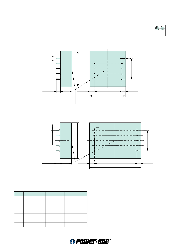
Mechanical data
Tolerances
±
0.3 mm (0.012") unless otherwise indicated.
European
Projection
IMR 25...40 Series
25...40 Watt DC-DC Converters
70 (2.75")
52.5 (2.07")
10 (0.4")
7.5 (0.3")
23 (0.9")
4.5 (0.18")
70 (2.75")
1
.
5 (0.06")
1
2
7
6
5
4
3
S09039
5 x 10 (0.4")
Measuring point
of case temperature
T
C
IMR 25 triple output units and IMR 40
100 (3.94")
82.5 (3.25")
1
2
7
6
5
4
3
S09040
SD
10 (0.4")
7.5 (0.3")
23 (0.9")
4.5 (0.18")
70 (2.75")
1
.
5 (0.06")
5 x 10 (0.4")
Measuring point
of case temperature
T
C
IMR 25 single and dual outputs units
Pin allocation
Pin
Single output Dual output
Triple output
1
Vi+
Vi+
Vi+
2
Vi≠
Vi≠
Vi≠
3
Vo+
Vo+
Vo1+
4
Vo+
Vo+
COM
5
Vo≠
COM
Vo2+
6
Vo≠
COM
COM
7
n.c.
Vo≠
Vo3≠