P
Q
Q
D
F
K
E
M
J
C
A
L
G
H
H
B
J
J
(2 TYP.)
R - M4 THD
(3 TYP.)
N - DIA.
(3 TYP.)
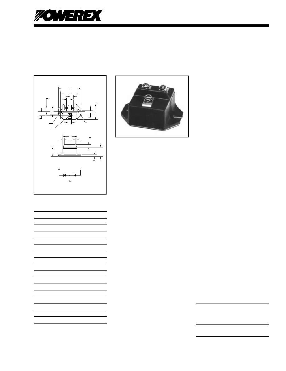
Dimension
Inches
Millimeters
A
2.106
53.5
B
1.705�0.008
43.3�0.2
C
1.437
36.5
D
1.299
33
E
0.925
23.5
F
0.866
22
G
0.551
14
H
0.354
9
J
0.315
8
K
0.276
7
L
0.236 R
R6
M
0.209
5.3
N
0.209 Dia.
Dia. 5.3
P
0.177
4.5
Q
0.138
3.5
R
M4 Metric
M4
CN--Common Anode Diode Module
CC--Common Cathode Diode Module
Description:
Powerex Super Fast Recovery
Dual Diode Modules are designed
for use in applications requiring
high speed rectification or voltage
clamping in isolated packaging.
The modules are insulated for
easy mounting onto a common
heatsink with other components.
They consist of two diodes
connected in either a common
cathode (CC) or a common
anode (CN) configuration.
Features:
Isolated Mounting
Metal Baseplate
Low Thermal Impendance
trr = 200ns, Maximum
Applications:
Battery Supplies
Free Wheeling Diodes
Motor Control Inventers
UPS Inventers
Ordering Information:
Select the complete ten digit
module part number you desire
from the table below.
Example: CC2406020N is a
600 Volt, 20 Ampere, trr = 200ns
Common Cathode Super Fast
Recovery Diode Module.
Current Current
Voltage
Rating
Recovery
Volts Amperes
Time
Type
(x100)
(x10)
(200ns)
CC24
03
02
ON
CN24
06
D-41
Powerex, Inc., 200 Hillis Street, Youngwood, Pennsylvania 15697-1800 (724) 925-7272
Super Fast Recovery
Dual Diode Modules
20 Amperes/300-600 Volts
CC24_ _020N
CN24_ _020N
Outline Drawing
CN24_ _020N, CC24_ _020N
Super Fast Recovery
Dual Diode Modules
20 Amperes/300-600 Volts

D-42
Powerex, Inc., 200 Hillis Street, Youngwood, Pennsylvania 15697-1800 (724) 925-7272
CC24_ _020N, CN24_ _020N
Super Fast Recovery Dual Diode Modules
20 Amperes/300-600 Volts
Absolute Maximum Ratings
CC2403020N
CC2406020N
Characteristics
Symbol
CN2403020N
CN2406020N
Units
Peak Reverse Blocking Voltage
VRRM
300
600
Volts
Transient Peak Reverse Blocking Voltage (Non-Repetitive), t < 5ms
VRSM
360
720
Volts
DC Reverse Blocking Voltage
VR(DC)
240
480
Volts
DC Current, TC = 90�C
IF(DC)
20
20
Amperes
Peak One-Cycle Surge (Non-Repetitive) On-State Current (60Hz)
IFSM
400
400
Amperes
Peak One-Cycle Surge (Non-Repetitive) On-State Current (50Hz)
IFSM
365
365
Amperes
I2t (for Fusing), 8.3 milliseconds
I2t
667
667
A2sec
Storage Temperature
TSTG
-40 to 125
-40 to 125
�C
Operating Temperature
Tj
-40 to 150
-40 to 150
�C
Maximum Mounting Torque M4 Mounting Screw
--
12
12
in.-lb.
Maximum Mounting Torque M5 Terminal Screw
--
17
17
in.-lb.
Module Weight (Typical)
--
90
90
Grams
V Isolation
VRMS
2500
2500
Volts
Electrical and Thermal Characteristics,
Tj = 25�C unless otherwise specified
Characteristics
Symbol
Test Conditions
CC24_ _020N/CN24_ _020N
Units
Blocking State Maximums
Reverse Leakage Current, Peak
IRRM
Tj = 125�C, VRRM = Rated
10
mA
Conducting State Maximums
Peak On-State Voltage
VFM
IFM = 20A
2.5
Volts
Switching Maximums
Reverse Recovery Time
trr
IFM = 20A
200
ns
di/dt = -50 A/ s, VR = 1/2 VRRM
Thermal Maximums
Thermal Resistance, Junction-to-Case
R (J-C)
Per Module
1.2
�C/Watt
Thermal Resistance, Case-to-Sink (Lubricated)
R (C-S)
Per Module
0.3
�C/Watt
INSTANTANEOUS ON-STATE CURRENT, I
FM
,
(AMPERES)
MAXIMUM
ON-STATE CHARACTERISTICS
10
0
10
1
10
2
10
3
INSTANTANEOUS ON-STATE VOLTAGE, V
FM
, (VOLTS)
1.0
1.8
2.6
3.4
4.2
T
j
= 25
o
C
MAXIMUM
ALLOWABLE CASE TEMPERATURE
AVERAGE ON-STATE CURRENT, I
F(AV)
,
(AMPERES)
MAXIMUM ALLOWABLE CASE TEMPERATURE, T
C
, (
o
C)
0
4
32
12
16
28
8
20
24
40
50
60
70
80
90
100
110
120
130
140
150
RESISTIVE
INDUCTIVE
LOAD
DC
SINGLE-PHASE
THREE-PHASE
OPERATION
MAXIMUM
ON-STATE POWER DISSIPATION
AVERAGE ON-STATE CURRENT, I
F(AV)
,
(AMPERES)
MAXIMUM POWER DISSIPATION, P
AV(MAX)
, (WATTS)
0
10
80
30
50
60
0
50
100
150
200
250
20
40
70
RESISTIVE
INDUCTIVE
LOAD
DC
SINGLE-PHASE
THREE-PHASE
OPERATION