 | –≠–ª–µ–∫—Ç—Ä–æ–Ω–Ω—ã–π –∫–æ–º–ø–æ–Ω–µ–Ω—Ç: CE420830 | –°–∫–∞—á–∞—Ç—å:  PDF PDF  ZIP ZIP |
Dimension
Inches
Millimeters
A
3.386
86
B
2.913±0.012
74±0.3
C
2.441
62
D
1.772±0.008
45±0.2
E
1.220
31
F
1.122
28.5
G
1.063
27
H
0.866
22
J
0.787
20
K
0.276
7
L
0.236
6
M
0.217±0.008 Dia. 5.5±0.2 Dia.
N
M5 Metric
M5
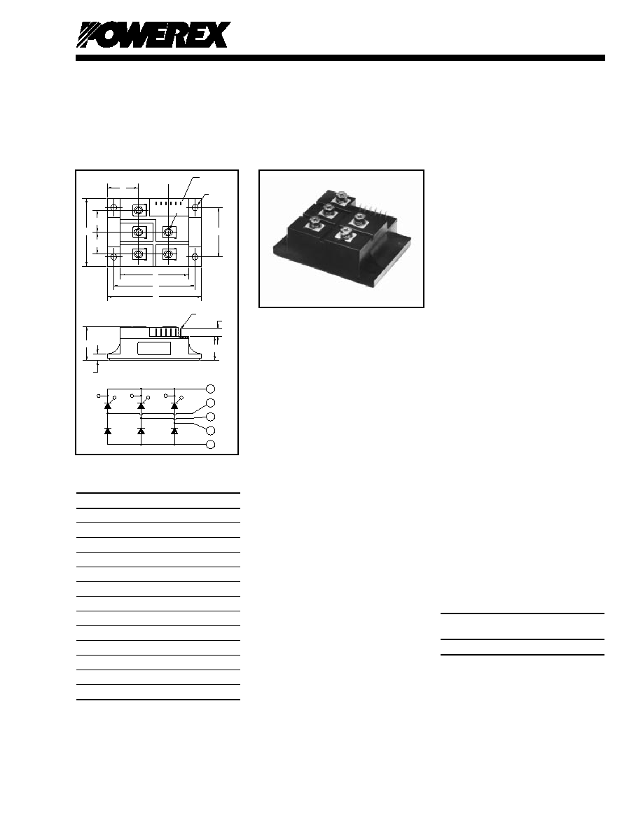
Description:
Powerex Three-Phase SCR/Diode
Bridge Modules are designed for
use in applications requiring vari-
able DC Voltage control from AC
mains. The modules are isolated
for easy mounting with other com-
ponents on common heatsinks.
Features:
Isolated Mounting
Glass Passivated Chips
dv/dt = 500V/ s
Metal Baseplate
Low Thermal Impedance
Quick Connect Signal Terminals
Applications:
Battery Supplies
AC and DC Motor Control
Furnace Control
Ordering Information:
Select the complete eight digit
module part number you desire
from the table below.
Example: CE420830 is a
800 Volt, 30 Ampere Three-Phase
SCR/Diode Bridge Module.
Voltage
Current Rating
Type
Volts (x100)
Amperes (30)
CE42
08
30
SD-45
Powerex, Inc., 200 Hillis Street, Youngwood, Pennsylvania 15697-1800 (724) 925-7272
Three-Phase SCR/Diode
Bridge Modules
30 Amperes/800 Volts
CE420830
Outline Drawing
CE420830
Three-Phase SCR/Diode
Bridge Modules
30 Amperes/800 Volts
E
L
K
D
H
A
B
C
C
J
J
F
N
T
S
R
GT
KT
GS
KS
KR
GR
P
.110 TAB
N - M5 THD.
(5 TYP.)
M - DIA.
(4 TYP.)
GR
KR
GS
KS
GT
KT
N
P
T
S
R

SD-46
Powerex, Inc., 200 Hillis Street, Youngwood, Pennsylvania 15697-1800 (724) 925-7272
CE420830
Three-Phase SCR/Diode Bridge Modules
30 Amperes/800 Volts
Absolute Maximum Ratings
Characteristics
Symbol
CE420830
Units
Peak Forward Blocking Voltage
VDRM
800
Volts
Transient Peak Forward Blocking Voltage (Non-Repetitive), t < 5ms
VDSM
960
Volts
DC Forward Blocking Voltage
VD(DC)
640
Volts
Peak Reverse Blocking Voltage
VRRM
800
Volts
Transient Peak Reverse Blocking Voltage (Non-Repetitive), t < 5ms
VRSM
960
Volts
DC Reverse Blocking Voltage
VR(DC)
640
Volts
DC Output Current, TC = 80∞C
IO
30
Amperes
Peak One-Cycle Surge (Non-Repetitive) On-State Current (60Hz)
ITSM, IFSM
300
Amperes
Peak One-Cycle Surge (Non-Repetitive) On-State Current (50Hz)
ITSM, IFSM
275
Amperes
I2t (for Fusing), 8.3 milliseconds
I2t
378
A2sec
Critical Rate-of-Rise of On-State Current*
di/dt
100
Amperes/ s
Peak Gate Power Dissipation
PGM
5.0
Watts
Average Gate Power Dissipation
PG(AV)
0.5
Watts
Peak Forward Gate Voltage
VGFM
10
Volts
Peak Reverse Gate Voltage
VGRM
5.0
Volts
Peak Forward Gate Current
IGFM
2.0
Amperes
Storage Temperature
TSTG
-40 to 125
∞C
Operating Temperature
Tj
-40 to 125
∞C
Maximum Mounting Torque M5 Mounting Screw
--
17
in.-lb.
Maximum Mounting Torque M5 Terminal Screw
--
17
in.-lb.
Module Weight (Typical)
--
310
Grams
V Isolation
VRMS
2000
Volts
*Tj = 125∞C, IG = 0.5A, VD = 1/2 VDRM

SD-47
Powerex, Inc., 200 Hillis Street, Youngwood, Pennsylvania 15697-1800 (724) 925-7272
CE420830
Three-Phase SCR/Diode Bridge Modules
30 Amperes/800 Volts
Electrical and Thermal Characteristics,
Tj = 25∞C unless otherwise specified
Characteristics
Symbol
Test Conditions
CE420830
Units
Blocking State Maximums
Forward Leakage Current, Peak
IDRM
Tj = 125∞C, VDRM = Rated
4.0
mA
Reverse Leakage Current, Peak
IRRM
Tj = 125∞C, VRRM = Rated
4.0
mA
Conducting State Maximums
Peak On-State Voltage
VFM,VTM
IFM = 45A, ITM = 45A,
1.5
Volts
Switching Minimums
Critical Rate-of-Rise of Off-State Voltage
dv/dt
Tj = 125∞C, VD = 2/3 VDRM
500
Volts/ s
Thermal Maximums
Thermal Resistance, Junction-to-Case
R (J-C)
Per Module
1.8
∞C/Watt
Thermal Resistance, Case-to-Sink (Lubricated)
R (C-S)
Per Module
0.06
∞C/Watt
Gate Parameters Maximums
Gate Current-to-Trigger
IGT
VD = 6V, RL = 2
50
mA
Gate Voltage-to-Trigger
VGT
VD = 6V, RL = 2
2.0
Volts
Non-Triggering Gate Voltage
VGDM
Tj = 125∞C, VD = 1/2 VDRM
0.25
Volts

SD-48
Powerex, Inc., 200 Hillis Street, Youngwood, Pennsylvania 15697-1800 (724) 925-7272
CE420830
Three-Phase SCR/Diode Bridge Modules
30 Amperes/800 Volts
INSTANTANEOUS ON-STATE CURRENT, I
TM
,
(AMPERES)
MAXIMUM
ON-STATE CHARACTERISTICS
0.5
10
0
2.5
10
1
10
2
10
3
T
j
= 125
o
C
INSTANTANEOUS ON-STATE VOLTAGE, V
TM
, (VOLTS)
2.0
1.5
1.0
CYCLES AT 60 H
Z
MAXIMUM PEAK SURGE (NON-REPETITIVE)
CURRENT, I
TSM
, (AMPERES)
MAXIMUM ALLOWABLE PEAK SURGE
(NON-REPETITIVE) CURRENT
0
10
1
10
2
10
0
100
200
300
400
500
TIME, t, (SECONDS)
TRANSIENT THERMAL IMPEDANCE
CHARACTERISTICS (JUNCTION-TO-CASE)
0
10
-3
2.5
10
-2
10
-1
10
0
TRANSIENT THERMAL IMPEDANCE, Z
(J-C)
(t), (
o
C/WATT)
10
0
10
1
2.0
1.5
1.0
0.5
MAXIMUM ALLOWABLE CASE TEMPERATURE
(THREE PHASE BRIDGE CONNECTION)
DC OUTPUT CURRENT, I
O
, (AMPERES)
MAXIMUM ALLOWABLE CASE TEMPERATURE, T
C
, (
o
C)
0
130
360
o
RESISTIVE,
INDUCTIVE
LOAD
5
10
15
20
25
30
35
40
120
110
100
90
= 30
o
90
o
60
o
120
o
MAXIMUM ON-STATE POWER DISSIPATION
(THREE PHASE BRIDGE CONNECTION)
DC OUTPUT CURRENT, I
O
, (AMPERES)
MAXIMUM POWER DISSIPATION, P
AV(MAX)
, (WATTS)
0
80
360
o
RESISTIVE,
INDUCTIVE
LOAD
5
10
15
20
25
30
35
40
70
60
50
40
30
20
10
0
= 30
o
90
o
60
o
120
o