Powerex, Inc., 200 Hillis Street, Youngwood, Pennsylvania 15697-1800 (724) 925-7272
IntellimodTM Module
Three Phase + Brake
IGBT Inverter Output
50 Amperes/1200 Volts
PM50RSD120
1
Description:
Powerex IntellimodTM Intelligent
Power Modules are isolated base
modules designed for power
switching applications operating
at frequencies to 20kHz. Built-in
control circuits provide optimum
gate drive and protection for the
IGBT and free-wheel diode
power devices.
Features:
Complete Output Power
Circuit
Gate Drive Circuit
Protection Logic
≠ Short Circuit
≠ Over Current
≠ Over Temperature
≠ Under Voltage
Low Loss Using 4th Generation
IGBT Chip
Applications:
Inverters
UPS
Motion/Servo Control
Power Supplies
Ordering Information:
Example: Select the complete
part number from the table below
-i.e. PM50RSD120 is a 1200V,
50 Ampere IntellimodTM Intelligent
Power Module.
Type
Current Rating
V
CES
Amperes
Volts (x 10)
PM
50
120
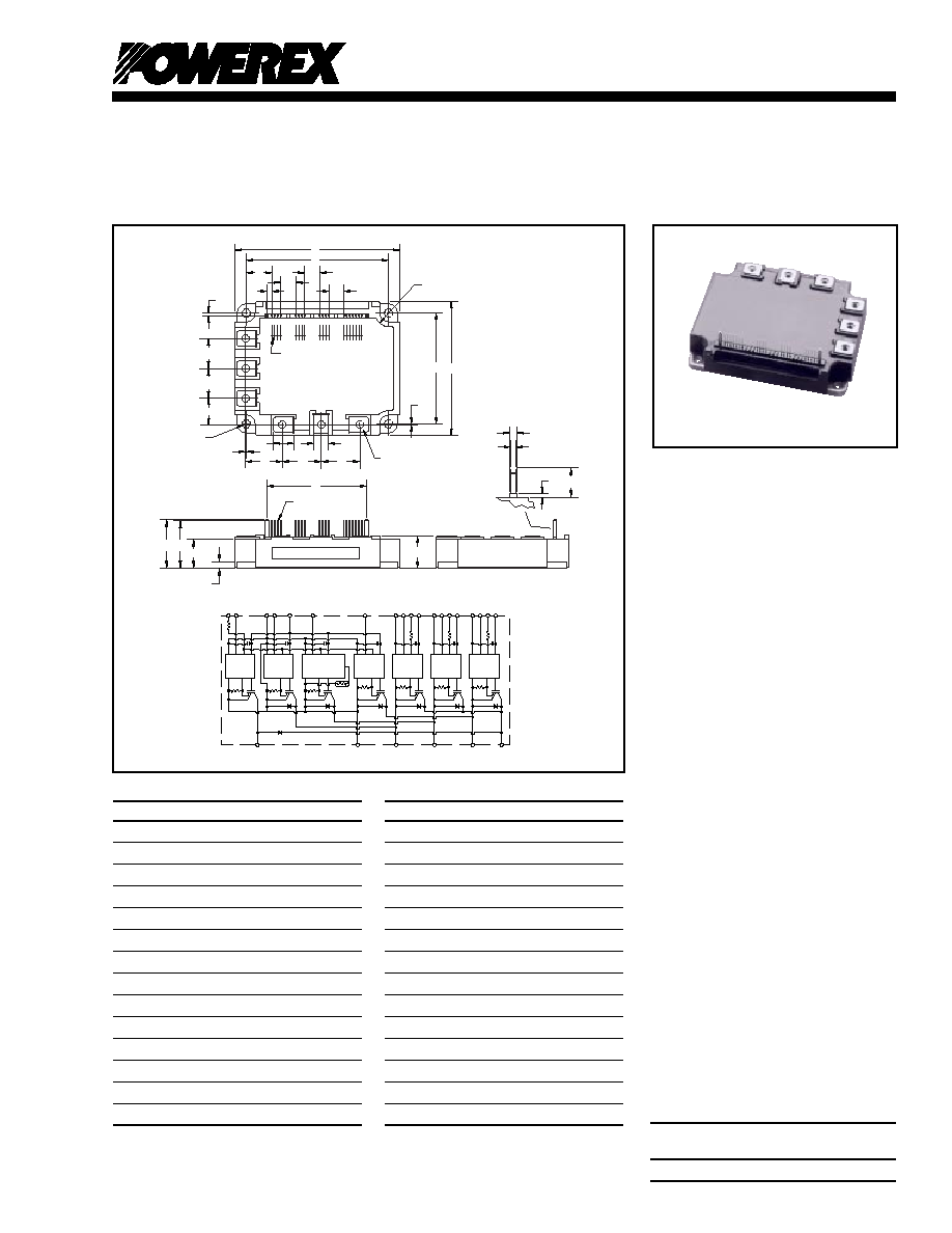
Outline Drawing and Circuit Diagram
Dimensions
Inches
Millimeters
A
4.33
±
0.04
110.0
±
1.0
B
3.74
±
0.02
95.0
±
0.5
C
3.50
±
0.04
89.0
±
1.0
E
2.91
±
0.02
74.0
±
0.5
F
2.62
66.44
G
1.28
32.6
H
1.24
31.6
J
1.02
26.0
K
0.94
24.0
L
0.87 +0.04/-0.02 22.0 +1.0/-0.5
M
0.79
20.0
N
0.76
19.4
P
0.18
4.5
Q
0.10
2.54
Dimensions
Inches
Millimeters
R
0.67
17.02
S
0.67
17.02
T
0.52
13.2
U
0.39
10.0
V
0.16
4.0
W
0.02
0.5
Y
0.24 Rad.
Rad. 6.0
Z
0.22 Dia.
Dia.5.5
AA
M5
M5
AB
0.13
3.22
AC
0.06
1.6
AD
0.08
±
0.02
2.0
±
0.5
AG
0.020.01
0.5
±
0.3
AH
0.47
12.0
S
A
AH
U
Z
(4 PLACES)
F
AB
P
Q
(2 PLACES)
AC
L
B
M
M
AD
AG
J
J
E
U
U
U
R
A
N
G
H
V
C
T
1.
2.
3.
4.
5.
6.
7.
8.
9.
V
V
V
V
V
V
V
10.
11.
12.
13.
14.
15.
16.
U
U
V
V
W
W
WPC
UPI
VPI
WPI
NC
NI
P
N
P
P
N
N
UPC
F
O
V
VPC
7 8
9
10
11
13 15
1 2 3 4
5 6
N
V
W
U
BP
17.
18.
19.
Br
WF
O
O
VF
O
UF
AA - THD
AD
12
14 16 18
17 19
(19 TYP.)
Y (4 PLACES)
W SQ. PIN
(6 PLACES)
V
V
CC
S
I
GND
GND
OUT
UPI
V
U
FO
UP
UPC
F
O
IN
V
CC
S
I
GND
GND
OUT
F
O
IN
V
CC
S
I
GND
GND
OUT
F
O
IN
V
V
FO
V
V
FO
VPI
V
VP
VPC
WPI
W
WP
WPC
V
CC
S
I
GND
GND
OUT
F
O
IN
V
CC
S
I
GND
GND
OUT
F
O
IN
U
N
V
CC
S
I
GND
GND
OUT
F
O
IN
V
V
W
N
V
NI
N
NC
TEMP
F
O
P
U
V
W
N
B
V
CC
S
I
GND
GND
OUT
F
O
IN
R
B

PM50RSD120
IntellimodTM Module
Three Phase + Brake IGBT Inverter Output
50 Amperes/1200 Volts
2
Powerex, Inc., 200 Hillis Street, Youngwood, Pennsylvania 15697-1800 (724) 925-7272
Absolute Maximum Ratings,
T
j
= 25
∞
C unless otherwise specified
Characteristics
Symbol
PM50RSD120
Units
Power Device Junction Temperature
T
j
-20 to 150
∞
C
Storage Temperature
T
stg
-40 to 125
∞
C
Case Operating Temperature
*
T
C
-20 to 100
∞
C
Mounting Torque, M5 Mounting Screws
--
31
in-lb
Mounting Torque, M5 Main Terminal Screws
--
31
in-lb
Module Weight (Typical)
--
560
Grams
Supply Voltage Protected by OC and SC
V
CC(prot.)
800
Volts
(V
D
= 13.5 - 16.5V, Inverter Part) T
j
= 125
∞
C Start
Isolation Voltage, AC 1 minute, 60Hz Sinusoidal
V
ISO
2500
Volts
IGBT Inverter Sector
Collector-Emitter Voltage (V
D
= 15V, V
CIN
= 15V)
V
CES
1200
Volts
Collector Current,
±
(T
C
= 25
∞
C)
I
C
50
Amperes
Peak Collector Current,
±
(T
C
= 25
∞
C)
I
CP
100
Amperes
Supply Voltage (Applied between P - N)
V
CC
800
Volts
Supply Voltage, Surge (Applied between P - N)
V
CC(surge)
1000
Volts
Collector Dissipation (T
C
= 25
∞
C)
P
C
328
Watts
IGBT Brake Sector
Collector-Emitter Voltage (V
D
= 15V, V
CIN
= 15V)
V
CES
1200
Volts
Collector Current,
±
(T
C
= 25
∞
C)
I
C
15
Amperes
Peak Collector Current,
±
(T
C
= 25
∞
C)
I
CP
30
Amperes
FWDi Rated DC Reverse Voltage (T
C
= 25
∞
C)
V
R(DC)
1200
Volts
FWDi Forward Current (T
C
= 25
∞
C)
I
F
15
Amperes
Collector Dissipation (T
C
= 25
∞
C)
P
C
201
Watts
Control Sector
Supply Voltage Applied between (V
UP1
-V
UPC
, V
VP1
-V
VPC
, V
WP1
-V
WPC
, V
N1
-V
NC
)
V
D
20
Volts
Input Voltage Applied between (U
P
-V
UPC
, V
P
-V
VPC
, W
P
-V
WPC
, U
N
,
V
N
, W
N
, B
r
-V
NC
)
V
CIN
20
Volts
Fault Output Supply Voltage Applied between
V
FO
20
Volts
(U
FO
-V
UPC
, V
FO
-V
VPC
, W
FO
-V
WPC
, F
O
-V
NC
)
Fault Output Current (U
FO
, V
FO
, W
FO
, F
O
)
I
FO
20
mA
63MM
T
C
*
T
C
Measure Point

3
PM50RSD120
IntellimodTM Module
Three Phase + Brake IGBT Inverter Output
50 Amperes/1200 Volts
Powerex, Inc., 200 Hillis Street, Youngwood, Pennsylvania 15697-1800 (724) 925-7272
Electrical and Mechanical Characteristics,
T
j
= 25
∞
C unless otherwise specified
Characteristics
Symbol
Test Conditions
Min.
Typ.
Max.
Units
IGBT Inverter Sector
Collector Cutoff Current
I
CES
V
CE
= V
CES
, T
j
= 25
∞
C, V
D
= 15V
--
--
1.0
mA
V
CE
= V
CES
, T
j
= 125
∞
C, V
D
= 15V
--
--
10
mA
Diode Forward Voltage
V
EC
-I
C
= 50A, V
D
= 15V, V
CIN
= 15V
--
2.5
3.5
Volts
Collector-Emitter Saturation Voltage
V
CE(sat)
V
D
= 15V, V
CIN
= 0V, I
C
= 50A,
--
2.4
3.2
Volts
Pulsed, T
j
= 25
∞
C
V
D
= 15V, V
CIN
= 0V, I
C
= 50A,
--
2.1
2.8
Volts
Pulsed, T
j
= 125
∞
C
Inductive Load Switching Times
t
on
0.5
1.0
2.5
µ
S
t
rr
V
D
= 15V, V
CIN
= 0 ~ 15V
--
0.15
0.3
µ
S
t
C(on)
V
CC
= 600V, I
C
= 50A
--
0.4
1.0
µ
S
t
off
T
j
= 125
∞
C, Inductive Load
--
2.5
3.5
µ
S
t
C(off)
--
0.7
1.2
µ
S
IGBT Brake Sector
Collector Cutoff Current
I
CES
V
CE
= V
CES
, T
j
= 25
∞
C, V
D
= 15V
--
--
1.0
mA
V
CE
= V
CES
, T
j
= 125
∞
C, V
D
= 15V
--
--
10
mA
FWDi Forward Voltage
V
FM
I
F
= 15A
--
2.5
3.5
Volts
Collector-Emitter Saturation Voltage
V
CE(sat)
V
D
= 15V, V
CIN
= 0V, I
C
= 15A,
--
2.5
3.3
Volts
Pulsed, T
j
= 25
∞
C
V
D
= 15V, V
CIN
= 0V, I
C
= 15A,
--
2.2
3.2
Volts
Pulsed, T
j
= 125
∞
C
Control Sector
Over Current Trip Level Inverter Part
OC
T
j
= 25
∞
C
93
157
--
Amperes
(V
D
= 15V)
T
j
= 125
∞
C
59
--
--
Amperes
Over Current Trip Level Brake Part
OC
-20
∞
C
T
j
125
∞
C, V
D
= 15V
22
--
--
Amperes
Short Circuit Trip Level Inverter Part
SC
-20
∞
C
T
j
125
∞
C, V
D
= 15V
--
183
--
Amperes
Short Circuit Trip Level Brake Part
--
95
--
Amperes
Over Current Delay Time
t
off(OC)
V
D
= 15V
--
10
--
µ
S
Over Temperature Protection (V
D
= 15V)
OT
Trip Level
111
118
125
∞
C
(Lower Arm)
OT
R
Reset Level
--
100
--
∞
C
Supply Circuit Under Voltage Protection
UV
Trip Level
11.5
12.0
12.5
Volts
(-20
T
j
125
∞
C)
UV
R
Reset Level
--
12.5
--
Volts
Circuit Current
I
D
V
D
= 15V, V
CIN
= 15V, V
N1
-V
NC
--
44
60
mA
V
D
= 15V, V
CIN
= 15V, V
XP1
-V
XPC
--
13
18
mA
Input ON Threshold Voltage
V
CIN(on)
Applied between U
P
-V
UPC
, V
P
-V
VPC
,
1.2
1.5
1.8
Volts
Input OFF Threshold Voltage
V
CIN(off)
W
P
-V
WPC
, U
N
, V
N
, W
N
,
B
r
-V
NC
1.7
2.0
2.3
Volts
Fault Output Current*
I
FO(H)
V
D
= 15V, V
CIN
= 15V
--
--
0.01
mA
I
FO(L)
V
D
= 15V, V
CIN
= 15V
--
10
15
mA
Minimum Fault Output Pulse Width*
t
FO
V
D
= 15V
1.0
1.8
--
mS
*Fault output is given only when the internal OC, SC, OT and UV protections schemes of either upper or lower arm device operate to protect it.

PM50RSD120
IntellimodTM Module
Three Phase + Brake IGBT Inverter Output
50 Amperes/1200 Volts
4
Powerex, Inc., 200 Hillis Street, Youngwood, Pennsylvania 15697-1800 (724) 925-7272
Thermal Characteristics
Characteristic
Symbol
Condition
Min.
Typ.
Max.
Units
Junction to Case Thermal Resistance
R
th(j-c)Q
Each IGBT
--
--
0.38
∞
C/Watt
Inverter Part
R
th(j-c)F
Each FWDi
--
--
0.70
∞
C/Watt
R
th(j-c¥)Q
Each IGBT*
--
--
0.23**
∞
C/Watt
R
th(j-c¥)F
Each FWDi*
--
--
0.36**
∞
C/Watt
Junction to Case Thermal Resistance
R
th(j-c)Q
Each IGBT
--
--
0.62
∞
C/Watt
Brake Part
R
th(j-c)F
Each FWDi
--
--
1.33
∞
C/Watt
R
th(j-c¥)Q
Each IGBT*
--
--
0.40**
∞
C/Watt
R
th(j-c¥)F
Each FWDi*
--
--
0.77**
∞
C/Watt
Contact Thermal Resistance
R
th(c-f)
Case to Fin Per Module,
--
--
0.027
∞
C/Watt
Thermal Grease Applied
*T
C
measured point is just under the chips.
**If you use this value, R
th(f-a)
should be mesured just under the chips.
Recommended Conditions for Use
Characteristic
Symbol
Condition
Value
Units
Supply Voltage
V
CC
Applied across P-N Terminals
0 ~ 800
Volts
Control Supply Voltage***
V
D
Applied between V
UP1
-V
UPC
,
15
±
1.5
Volts
V
N1
-V
NC
, V
VP1
-V
VPC
, V
WP1
-V
WPC
Input ON Voltage
V
CIN(on)
Applied between U
P
-V
UPC
, V
P
-V
VPC
,
0 ~ 0.8
Volts
Input OFF Voltage
V
CIN(off)
W
P
-V
WPC
, U
N,
V
N
, W
N,
B
r
-V
NC
4.0 ~ V
D
Volts
PWM Input Frequency
f
PWM
Using Application Circuit
0 ~ 20
kHz
Minimum Dead Time
t
DEAD
Input Signal
3.0
µ
S
***With ripple satisfying the following conditions: dv/dt
±
5v/
µ
s, Variation
2V peak to peak.

5
PM50RSD120
IntellimodTM Module
Three Phase + Brake IGBT Inverter Output
50 Amperes/1200 Volts
Powerex, Inc., 200 Hillis Street, Youngwood, Pennsylvania 15697-1800 (724) 925-7272
0
1.0
2.0
3.0
SATURATION VOLTAGE
CHARACTERISTICS (TYPICAL)
COLLECTOR CURRENT, I
C
, (AMPERES)
SATURATION VOLTAGE, V
CE(sat)
, (VOLTS)
0
60
20
40
V
D
= 15V
V
CIN
= 0V
T
j
= 25
o
C
T
j
= 125
o
C
2.5
1.5
0.5
10
0
10
1
10
2
DIODE FORWARD CHARACTERISTICS
(TYPICAL)
DIODE FORWARD VOLTAGE, V
EC
, (VOLTS)
DIODE CURRENT, -I
C
, (AMPERES)
0.5
1.0
1.5
2.0
2.5
T
j
= 25
o
C
T
j
= 125
o
C
0
V
D
= 15V
10
0
10
1
10
2
10
-1
COLLECTOR CURRENT, I
C
, (AMPERES)
SWITCHING TIMES, t
on
, t
off
, (
µ
s)
SWITCHING TIME VS.
COLLECTOR CURRENT (TYPICAL)
t
on
10
0
10
1
t
off
V
CC
= 600V
V
D
= 15V
T
j
= 25
o
C
Tj
= 125
o
C
10
0
10
1
10
2
10
-1
COLLECTOR CURRENT, I
C
, (AMPERES)
SWITCHING TIMES, t
c(on)
, t
c(off)
, (
µ
s)
SWITCHING TIME VS.
COLLECTOR CURRENT (TYPICAL)
t
c(on)
10
0
10
1
t
c(off)
t
c(off)
V
CC
= 600V
V
D
= 15V
T
j
= 25
o
C
T
j
= 125
o
C
10
0
10
1
10
2
10
-2
COLLECTOR CURRENT, -I
C
, (AMPERES)
REVERSE RECOVERY TIME, t
rr
, (
µ
S)
REVERSE RECOVERY CURRENT VS.
COLLECTOR CURRENT (TYPICAL)
10
-1
10
0
V
CC
= 600V
V
D
= 15V
INDUCTIVE LOAD
T
j
= 25
o
C
T
j
= 125
o
C
10
0
REVERSE RECOVERY CURRENT, I
rr
, (AMPERES)
10
1
10
2
t
rr
I
rr
0
0
40
60
80
100
CIRCUIT CURRENT VS.
CARRIER FREQUENCY
CARRIER FREQUENCY, f
C
, (kHz)
CIRCUIT CURRENT, I
D
, (mA)
5
10
15
20
25
T
j
= 25
o
C
N-SIDE
P-SIDE
20
INDUCTIVE LOAD
10
0
10
1
10
2
10
-1
SWITCHING LOSS, E
SW
, (mJ/PULSE)
SWITCHING LOSS CHARACTERISTICS
(TYPICAL)
10
0
10
1
V
CC
= 600V
V
D
= 15V
INDUCTIVE LOAD
T
j
= 25
o
C
T
j
= 125
o
C
E
sw(off)
E
sw(off)
E
sw(on)
E
sw(on)
TIME, (s)
TRANSIENT IMPEDANCE, Z
th(
j-c)
, (NORMALIZED VALUE)
TRANSIENT THERMAL
IMPEDANCE CHARACTERISTICS
(IGBT & FWDi - INVERTER PART)
10
1
10
-1
10
0
10
1
10
0
10
-1
10
-2
10
-3
STANDARD VALUE
R
th(j-c)Q
= 0.38
o
C/W (IGBT)
R
th(j-c)F
= 0.70
o
C/W (FWDi)
SINGLE PULSE
10
-2
10
-3
COLLECTOR CURRENT, I
C
, (AMPERES)
INDUCTIVE LOAD
0
1.0
2.0
3.0
COLLECTOR-EMITTER SATURATION
VOLTAGE (TYPICAL)
SUPPLY VOLTAGE, V
D
, (VOLTS)
SATURATION VOLTAGE, V
CE(sat)
, (VOLTS)
12
0
18
13
14
15
16
17
I
C
= 50A
T
j
= 25
o
C
T
j
= 125
o
C
1.5
2.5
0.5
Inverter Part