QIQ1245001
Powerex, Inc., 200 Hillis St., Youngwood 15697 (724) 925-7272
Low side Chopper IGBT Module
1200V 450A IGBT / 1200V 750A Fast Diode
Preliminary Page
1 4/22/2002
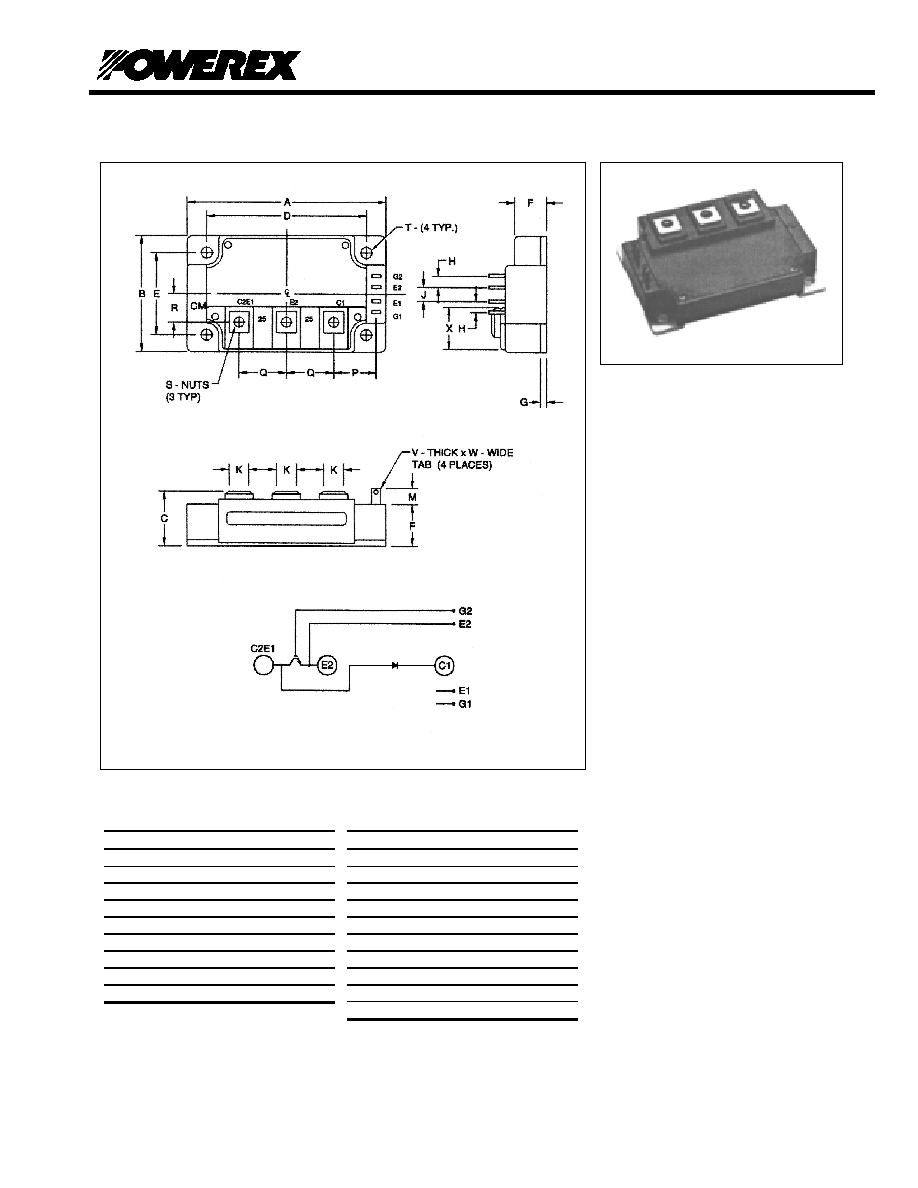
Outline Drawing and Circuit Diagram
n
Description:
Powerex Low Side Chopper
IGBT Module is designed
specially for customer applications. The
modules are isolated for easy mounting
with other components on a common
heatsink.
Features:
Low Drive Requirement
Low V
CE(sat)
Super Fast Diode
(3) F Series 150A 1200V
Trench Gate Chips per IGBT
(5) F Series 150A 1200V
Chips per Diode
Isolated Baseplate for Easy
Heat
Sinking
Al
2
O
3
DBC Ceramic
Low Thermal Impedance
Applications:
Choppers
Welding Power Supplies
Dim Inches
Millimeters
A 4.33 110.0
B 3.15
80.0
C 1.14+0.04/-0.02
29.0+1.0/-0.5
D
3.66
±
0.01 93.0
±
0.25
E
2.44
±
0.01 62.0
±
0.25
F 0.83
21.0
G 0.16
4.0
H 0.24
6.0
J 0.59
15.0
Dim Inches
Millimeters
K 0.55
14.0
M 0.33
8.5
P 0.94
24.0
Q 0.98
25.0
R 0.86 21.75
S M6
M6
T 0.26
Dia. 6.5
Dia.
V 0.02
0.5
W 0.11
2.79
X 1.08 27.35

QIQ1245001
Powerex, Inc., 200 Hillis St., Youngwood 15697 (724) 925-7272
Low side Chopper IGBT Module
1200V 450A IGBT / 1200V 750A Fast Diode
Preliminary Page
2 4/22/2002
Maximum Ratings, Tj=25
∞
∞
∞
∞
C unless otherwise specified
Ratings Symbol
QIQ1245001
Units
Collector- Emitter Voltage (G-E Short)
V
CES
1200 Volts
Gate- Emitter Voltage (C-E Short)
V
GES
±
20
Volts
Collector Current
I
C
450
Amperes
Peak Collector Current (Tj<= 150∞C)
I
CM
900*
Amperes
Diode Forward Current
I
FM
750
Amperes
Power Dissipation
P
d
TBD Watts
Junction Temperature
T
j
-40 to 150
∞
C
Storage Temperature
T
stg
-40 to 125
∞
C
Mounting
Torque
, M6 Terminal Screws
-
40
In-lb
Mounting Torque, M6 Mounting Screws
-
40
In-lb
Module Weight (Typical)
-
580
Grams
Isolation Voltage (Main Terminal to Baseplate, AC 1 min.)
V
RMS
2500 Volts
*
Pulse width and repetition rate should be such that the device junction temperature (Tj) does not exceed Tj(max) rating.
Static Electrical Characteristics, Tj=25
∞
∞
∞
∞
C unless otherwise specified
Characteristic Symbol
Test
Conditions
Min.
Typ.
Max.
Units
Collector Cutoff Current
I
CES
V
CE
=V
CES
V
GE
=0V
-
- 1.0 mA
Gate Leakage Current
I
GES
V
GE
=V
GES
V
CE
=0V -
- 60
µ
A
Gate-Emitter Threshold Voltage
V
GE(th)
I
C
=45mA, V
CE
=10V 5.0 6.0 7.0
Volts
Collector-Emitter Saturation Voltage
V
CE(sat)
I
C
=450A, V
GE
=15V - 1.8 2.4 Volts
I
C
=450A, V
GE
=15V,
T
j
=125
∞
C
- 1.9 - Volts
Total Gate Charge
Q
G
V
CC
=600V,
I
C
=450A, V
GS
=15V
- 4950 -
nC
Diode Forward Voltage
V
FM
I
F
=750A -
-
3.2
Volts
Dynamic Electrical Characteristics, Tj=25
∞
∞
∞
∞
C unless otherwise specified
Characteristic Symbol
Test
Conditions
Min.
Typ.
Max.
Units
Input Capacitance
C
ies
-
-
180
nF
Output Capacitance
C
oes
-
-
7.6
nF
Reverse Transfer Capacitance
C
res
V
GE
=0V
V
CE
=10V
f=1MHz
- - 4.5 nF
Turn on Delay time
t
d(on)
-
-
TBD
ns
Rise Time
t
r
-
-
TBD
ns
Turn-off Delay Time
t
d(off)
-
-
TBD
ns
Fall Time
t
f
V
CC
=600V
I
C
=450A
V
GE1
=V
GE2
=15V
R
G
=1.0
- -
TBD ns
Diode Reverse Recovery Time
trr
-
-
250
ns
Diode Reverse Recovery Charge
Qrr
I
F
=750A
- 44.0 -
µ
C
Thermal and Mechanical Characteristics, Tj=25
∞
∞
∞
∞
C unless otherwise specified
Characteristic Symbol
Test
Conditions
Min.
Typ.
Max.
Units
Thermal Resistance, Junction to Case
R
JC
Per IGBT
-
0.075
TBD
∞
C/W
Thermal Resistance, Junction to Case
R
JC
Per Diode
-
0.052
TBD
∞
C/W
Contact Thermal Resistance
R
CF
Per Module
-
0.01
-
∞
C/W