Preliminary
Powerex, Inc., Hillis Street, Youngwood, Pennsylvania 15697 (724) 925-7272
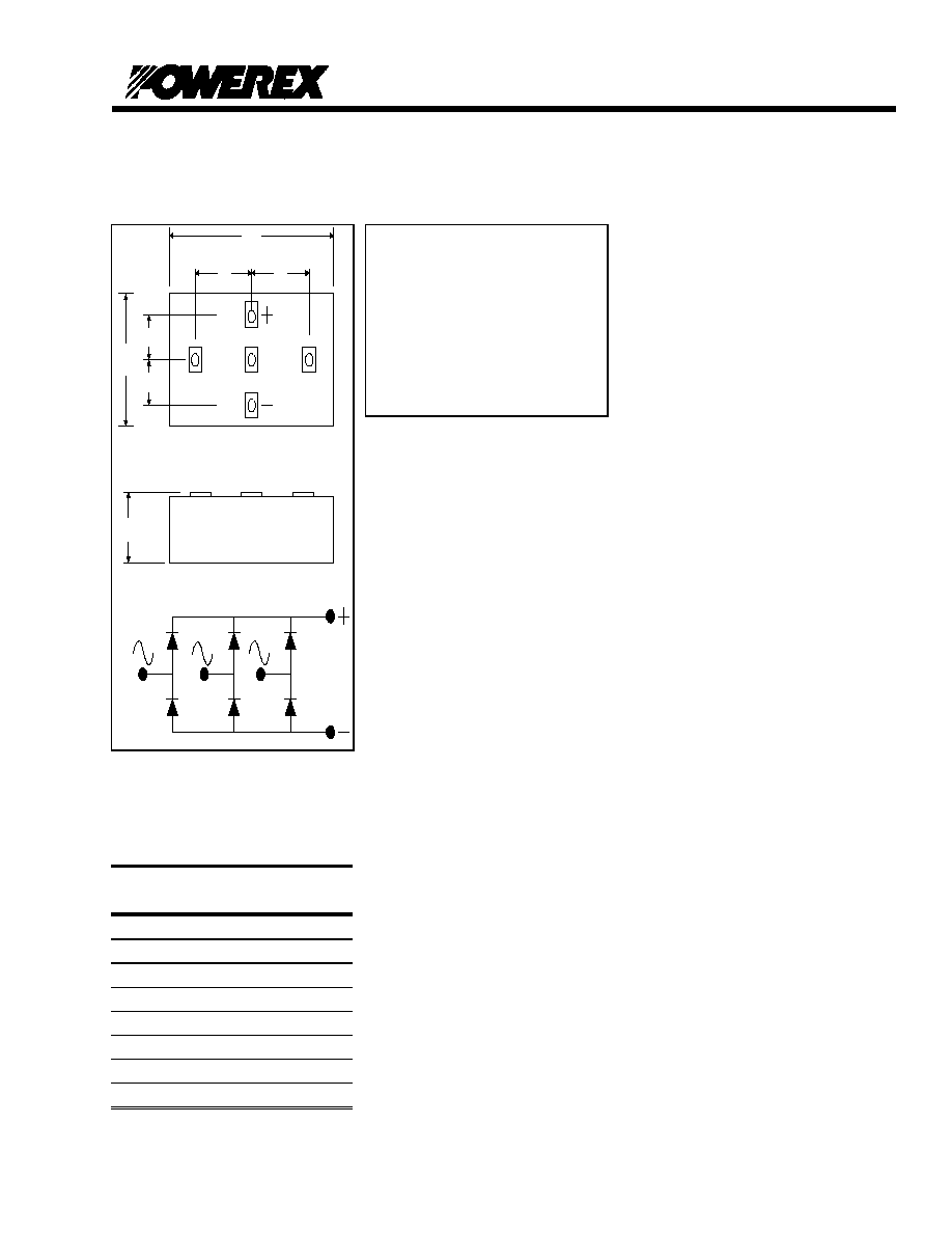
3 Phase Diode Bridge Module
120 Amp/Phase Up to 2400 Volts
Description:
Powerex 3 Phase Diode Modules are
designed for use in applications
requiring rectification and isolated
packaging. The modules are isolated
for easy mounting with other
components on a common heatsink.
Features:
n
Electrically Isolated Heatsinking
n
Metal Baseplate
n
Low Thermal Impedance
for Improved Current Capability
n
UL Recognized
Applications:
n
Battery Supplies
n
Bridge Circuits
n
AC & DC Motor Control
n
Rectifiers
QRE2412001
120 Amp/Phase
A
C
SIDE
D
TOP
T1
T2
T3
T1
T2
T3
E
E
F
F
Dimensions
Dimension
Inches
Metric
Min.
Max.
Min.
Max.
A
5.51
140
B
C
5.12
130
D
1.50
38
E
F
GO/
Note: Dimensions are for reference only.

Preliminary
Powerex, Inc., Hillis Street, Youngwood, Pennsylvania 15697 (724) 925-7272
QRD2412002
3 Phase Diode Bridge POW-R-BLOK
TM
Modules
120 Amperes /Phase Up to 2400 Volts
Absolute Maximum Ratings
Characteristics
Conditions
Symbol
Units
Repetitive Peak Reverse Blocking Voltage
V
RRM
up to 2400
V
Non-Repetitive Peak Reverse Blocking Voltage
V
RSM
V
RRM
+ 100
V
RMS Forward Current/Phase
I
F(RMS)
195
A
Average Forward Current/Phase
180
∞
Conduction, T
C
=106
∞
C
I
F(AV)
120
A
Peak Half Cycle Non-Repetitive Surge Current/Phase
t = 8.3mS, 100%V
RRM
reapplied
I
FSM
3500
A
Peak Half Cycle Non-Repetitive Surge Current/Phase
t = 10mS, 100%V
RRM
reapplied
I
FSM
3350
A
I
2
t for Fusing for One Cycle
t = 8.3mS, 100%V
RRM
reapplied
I
2
t
52,000
A
2
-sec
I
2
t for Fusing for One Cycle
t = 10mS, 100%V
RRM
reapplied
I
2
t
56,000
A
2
-sec
Operating Junction Temperature
T
J
-40 to +150
∞
C
Storage Temperature
T
stg
-40 to +150
∞
C
Maximum Mounting Torque, M6 Mounting Screw
- -
- -
2.84 to 3.43
Nm
Maximum Terminal Torque, M8 Terminal Screw
- -
- -
6.67 to 8.24
Nm
Module Weight, Typical
- -
- -
1.5
3.3
kg
lb.
V Isolation
V
RMS
6000
Vrms
QRE2412001
120 Amp/Phase

Preliminary
Powerex, Inc., Hillis Street, Youngwood, Pennsylvania 15697 (724) 925-7272
QRD2412002
3 Phase Diode Bridge POW-R-BLOK
TM
Modules
120 Amperes /Phase Up to 2400 Volts
Electrical and Thermal Characteristics, T
J
=25
∞
∞
C unless otherwise specified
Characteristics
Symbol
Test Conditions
Min.
Typ.
Max
Units
Peak Reverse Leakage Current
I
RRM
T
J
=150, Rated V
RRM
50
mA
Peak On-State Voltage
V
FM
I
FM
=500A
1.55
V
Threshold Voltage, Low-level
Slope Resistance, Low-level
V
(TO)1
r
T1
T
J
= 150
∞
C, I = 15%I
F(AV)
to
I
F(AV)
V
m
Threshold Voltage, High-level
Slope Resistance, High-level
V
(TO)2
r
T2
T
J
= 150
∞
C, I =
I
F(AV)
to I
FSM
V
m
V
FM
Coefficients, Full Range
T
J
= 150
∞
C, I = 15%I
F(AV)
to I
FSM
V
FM
=A + B Ln I
FM
+ C I
FM
+ D Sqrt I
FM
A =
B =
C =
D =
Thermal Characteristics
Characteristics
Symbol
Min.
Typ.
Max.
Units
Thermal Resistance, Junction to Case
R
JC
Per Module, both conducting
Per Diode, both conducting
------
------
0.20
∞
C/W
∞
C/W
Thermal Resistance, Case to Sink Lubricated
R
CS
Per Module
------
------
∞
C/W
QRE2412001
120 Amp/Phase
Preliminary
Powerex, Inc., Hillis Street, Youngwood, Pennsylvania 15697
POW-R-BLOK 3 Phase Diode Bridge Module
(724) 925-7272
120 Amperes/Phase up to 2400 Volts
000000
QRE2412001 120 Amp/Phase
3 Phase Diode Bridge Module
0
180
360
CONDUCTION ANGLE
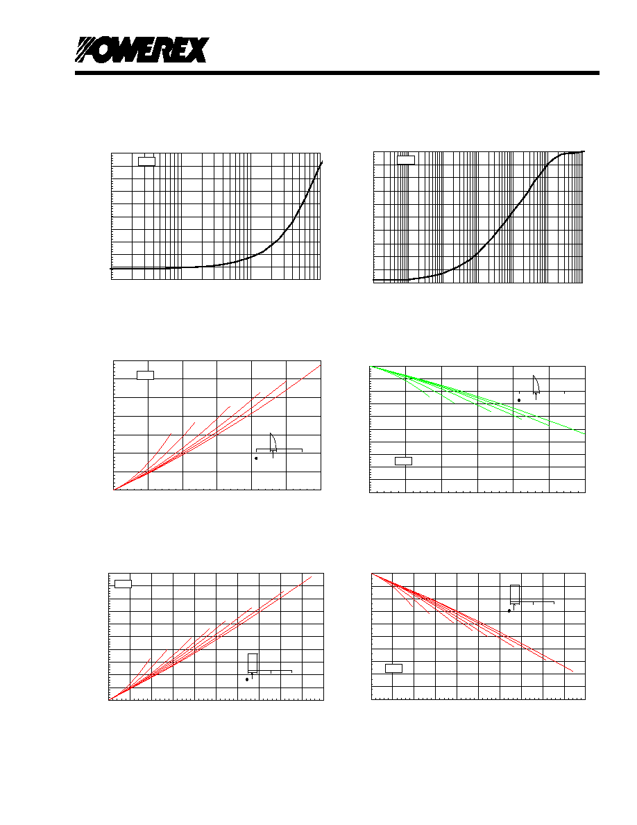
Maximum Allowable Case Temperature
120∞
90∞
60∞
30∞
15∞
180∞
100
105
110
115
120
125
130
135
140
145
150
0
20
40
60
80
100
120
Average On-State Current - It(av) - Amperes
Max. Case Temperature - Tcase - ∞C
(Sinusoidal Waveform)
GED01
0
180
360
CONDUCTION ANGLE
Maximum On-State Power Dissipation
90∞
60∞
30∞
120∞
180∞
270∞
15∞
360∞
0
20
40
60
80
100
120
140
160
180
200
0
20
40
60
80
100
120
140
160
180
200
Average On-State Current - It(av) - Amperes
Maximum Power Dissipation Per SCR - Watts
(Rectangular Waveform)
GED01
0
180
360
CONDUCTION ANGLE
Maximum On-State Power Dissipation
15∞
30∞
60∞
90∞
120∞
180∞
0
20
40
60
80
100
120
140
0
20
40
60
80
100
120
Average On-State Current - It(av) - Amperes
Maximum Power Dissipation Per SCR - Watts
(Sinusoidal Waveform)
GED01
Maximum Transient Thermal Impedance
.00000
.02000
.04000
.06000
.08000
.10000
.12000
.14000
.16000
.18000
.20000
.00010
.00100
.01000
.10000
1.00000
10.00000
100.00000
Time - t - Seconds
Thermal Impedance - Rjc - ∞C/W
(Junction to Case)
GED01
Maximum On-State Forward Voltage Drop
0.00
1.00
2.00
3.00
4.00
5.00
6.00
7.00
8.00
9.00
10.00
10.0
100.0
1000.0
10000.0
Instantaneous On-State Current - Itm - Amperes
On-State Voltage - Vtm - Volts
( Tj = 150 ∞C )
GED01
0
180
360
CONDUCTION ANGLE
Maximum Allowable Case Temperature
270∞
180∞
120∞
90∞
60∞
30∞
15∞
360∞C
100
105
110
115
120
125
130
135
140
145
150
0
20
40
60
80
100
120
140
160
180
200
Average On-State Current - It(av) - Amperes
Max. Case Temperature - Tcase - ∞C
(Rectangular Waveform)
GED01