 | –≠–ª–µ–∫—Ç—Ä–æ–Ω–Ω—ã–π –∫–æ–º–ø–æ–Ω–µ–Ω—Ç: 15KPA90 | –°–∫–∞—á–∞—Ç—å:  PDF PDF  ZIP ZIP |

15KPA17A
thru
15KPA280A
1
05024.R10 1/06
www.protekdevices.com
POWER TVS COMPONENT
Only One Name Means ProTek'TionTM
APPLICATIONS
Relay Drives
Motor (Start/Stop) Back EMF Protection
Module Lightning Protection
Secondary Lightning Protection for AC/DC
IEC COMPATIBILITY (EN61000-4)
61000-4-5 (Surge): 48A, 8/20µs - L3 (Line-Gnd), L4 (Line-Line) & L1 (Power)
FEATURES
15,000 Watts Peak Pulse Power per Line (tp=10/1000µs)
Unidirectional & Bidirectional Configurations
Easy Mounting to Printed Circuit Board
Available in Multiple Voltage Types Ranging From: 17V to 220V
RoHS Compliant in Lead-Free Versions (Exemption #7)
MECHANICAL CHARACTERISTICS
Molded Case
Weight 5 grams (Approximate)
Flammability Rating UL 94V-0
Available in Tin-Lead or Lead-Free Pure-Tin Plating(Annealed)
Solder Reflow Temperature:
Tin-Lead - Sn/Pb, 85/15: 240-245∞C
Pure-Tin - Sn, 100: 260-270∞C
Marking: Logo, Part Number & Date Code
Positive Terminal Marked with Band - Unidirectional Only
AXIAL LEAD
05024
APPLICATION
TYPICAL RELAY DRIVE PROTECTION
V
CC

2
www.protekdevices.com
05024.R10 1/06
15KPA17A
thru
15KPA280A
DEVICE CHARACTERISTICS
MAXIMUM RATINGS @ 25∞C Unless Otherwise Specified
Peak Pulse Power (tp =10/1000µs) - See Fig. 1
Forward Surge Rating (1/20 seconds) - See Note 2
SYMBOL
VALUE
1.0
Watts
Amps
200
Watts
UNITS
15000
I
F
P
PP
P
D
PARAMETER
Steady State Power Dissipation
-55 to +150
0
C
Storage Temperature
-55 to +150
0
C
T
J
Operating Temperature
T
STG
ELECTRICAL CHARACTERISTICS @ 25∞C Unless Otherwise Specified
PART
NUMBER
(Notes 1 & 2)
RATED
STAND-OFF
VOLTAGE
V
WM
VOLTS
BREAKDOWN
VOLTAGE
MAXIMUM
CLAMPING
VOLTAGE
(See Fig. 2)
@ 10/1000µs
V
C
@ I
PP
TEMPERATURE
COEFFICIENT
OF V
(BR)
qV
(BR)
mV/∞C
15KPA17
15KPA17A
15KPA18
15KPA18A
15KPA20
15KPA20A
15KPA22
15KPA22A
15KPA24
15KPA24A
15KPA26
15KPA26A
15KPA28
15KPA28A
15KPA30
15KPA30A
15KPA33
15KPA33A
15KPA36
15KPA36A
15KPA40
15KPA40A
15KPA43
15KPA43A
15KPA45
15KPA45A
15KPA48
15KPA48A
15KPA51
15KPA51A
15KPA54
15KPA54A
15KPA58
15KPA58A
15KPA60
15KPA60A
15KPA64
15KPA64A
15KPA70
15KPA70A
17.0
17.0
18.0
18.0
20.0
20.0
22.0
22.0
24.0
24.0
26.0
26.0
28.0
28.0
30.0
30.0
33.0
33.0
36.0
36.0
40.0
40.0
43.0
43.0
45.0
45.0
48.0
48.0
51.0
51.0
54.0
54.0
58.0
58.0
60.0
60.0
64.0
64.0
70.0
70.0
18.9
18.9
20.0
20.0
22.2
22.2
24.4
24.4
26.7
26.7
28.9
28.9
31.1
31.1
33.3
33.3
36.7
36.7
40.0
40.0
44.4
44.4
47.8
47.8
50.0
50.0
53.3
53.3
56.7
56.7
60.0
60.0
64.4
64.4
66.7
66.7
71.1
71.1
77.8
77.8
32.3V @ 464.0A
29.3V @ 512.0A
34.2V @ 439.0A
30.9V @ 485.0A
37.9V @ 396.0A
34.3V @ 437.0A
41.1V @ 365.0A
37.1V @ 404.0A
45.0V @ 333.0A
40.7V @ 369.0A
48.7V @ 308.0A
44.0V @ 341.0A
52.4V @ 286.0A
47.5V @ 316.0A
56.2V @ 267.0A
50.7V @ 296.0A
60.6V @ 248.0A
54.8V @ 274.0A
66.0V @ 227.0A
59.7V @ 251.0A
72.8V @ 206.0A
65.8V @ 228.0A
77.1V @ 195.0A
69.7V @ 215.0A
80.7V @ 186.0A
73.0V @ 205.0A
85.9V @ 175.0A
77.7V @ 193.0A
91.5V @ 164.0A
82.8V @ 181.0A
96.8V @ 155.0A
87.5V @ 171.0A
104.0V @ 144.0A
94.0V @ 160.0A
107.0V @ 140.0A
97.3V @ 154.0A
115.0V @ 130.0A
104.0V @ 144.0A
126.0V @ 119.0A
114.0V @ 132.0A
5000
5000
5000
5000
1500
1500
500
500
150
150
50
50
25
25
15
15
10
10
10
10
10
10
10
10
10
10
10
10
10
10
10
10
10
10
10
10
10
10
10
10
MAXIMUM
LEAKAGE
CURRENT
@V
WM
I
D
µA
19
17
20
18
24
21
27
24
30
27
32
29
35
31
27
34
42
38
46
41
51
46
55
50
57
52
62
56
66
60
70
63
76
68
78
71
84
76
92
83
MIN
V
(BR)
VOLTS
50
50
50
50
20
20
10
10
5
5
5
5
5
5
5
5
5
5
5
5
5
5
5
5
5
5
5
5
5
5
5
5
5
5
5
5
5
5
5
5
@I
T
mA

3
www.protekdevices.com
05024.R10 1/06
15KPA17A
thru
15KPA280A
ELECTRICAL CHARACTERISTICS @ 25∞C Unless Otherwise Specified
PART
NUMBER
(Notes 1 & 2)
RATED
STAND-OFF
VOLTAGE
V
WM
VOLTS
BREAKDOWN
VOLTAGE
MAXIMUM
CLAMPING
VOLTAGE
(See Fig. 2)
@ 10/1000µs
V
C
@ I
PP
TEMPERATURE
COEFFICIENT
OF V
(BR)
qV
(BR)
mV/∞C
15KPA75
15KPA75A
15KPA78
15KPA78A
15KPA85
15KPA85A
15KPA90
15KPA90A
15KPA100
15KPA100A
15KPA110
15KPA110A
15KPA120
15KPA120A
15KPA130
15KPA130A
15KPA150
15KPA150A
15KPA160
15KPA160A
15KPA170
15KPA170A
15KPA180
15KPA180A
15KPA200
15KPA200A
15KPA220
15KPA220A
15KPA240
15KPA240A
15KPA260
15KPA260A
15KPA280
15KPA280A
75.0
75.0
78.0
78.0
85.0
85.0
90.0
90.0
100.0
100.0
110.0
110.0
120.0
120.0
130.0
130.0
150.0
150.0
160.0
160.0
170.0
170.0
180.0
180.0
200.0
200.0
220.0
220.0
240.0
240.0
260.0
260.0
280.0
280.0
83.3
83.3
86.7
86.7
94.4
94.4
100.0
100.0
111.0
111.0
122.0
122.0
133.0
133.0
144.0
144.0
167.0
167.0
178.0
178.0
189.0
189.0
200.0
200.0
222.0
222.0
245.0
245.0
267.0
267.0
289.0
289.0
311.0
311.0
135.0V @ 111.0A
122.0V @ 123.0A
140.0V @ 107.0A
126.0V @ 119.0A
152.0V @ 99.0A
137.0V @ 109.0A
160.0V @ 94.0A
146.0V @ 103.0A
179.0V @ 84.0A
162.0V @ 93.0A
196.0V @ 77.0A
178.0V @ 84.0A
214.0V @ 70.0A
193.0V @ 78.0A
231.0V @ 65.0A
209.0V @ 72.0A
268.0V @ 56.0A
243.0V @ 62.0A
287.0V @ 52.0A
259.0V @ 58.0A
304.0V @ 49.0A
275.0V @ 55.0A
321.0V @ 47.0A
291.0V @ 52.0A
356.0V @ 42.0A
322.0V @ 47.0A
393.0V @ 38.0A
356.0V @ 42.0A
428.0V @ 35.0A
388.0V @ 39.0A
464.0V @ 32.0A
419.0V @ 36.0A
500.0V @ 30.0A
452.0V @ 33.0A
10
10
10
10
10
10
10
10
10
10
10
10
10
10
10
10
10
10
10
10
10
10
10
10
10
10
10
10
10
10
10
10
10
10
MAXIMUM
LEAKAGE
CURRENT
@V
WM
I
D
µA
100
89
104
93
113
102
120
109
134
121
147
133
161
145
174
157
202
183
216
195
229
207
242
219
269
243
297
269
324
293
352
317
378
342
MIN
V
(BR)
VOLTS
5
5
5
5
5
5
5
5
5
5
5
5
5
5
5
5
5
5
5
5
5
5
5
5
5
5
5
5
5
5
5
5
5
5
@I
T
mA
Note 1: Part numbers shown are unidirectional devices. Add a "CA" suffix to specify bidirectional devices, such as 15KPA20CA.
Note 2: V
F
= 7.5 Volts @ 200A, 8.3ms (1/2 Sine Wave) -
unidirectional devices only.

4
www.protekdevices.com
05024.R10 1/06
15KPA17A
thru
15KPA280A
GRAPHS
FIGURE 1
PEAK PULSE POWER VS PULSE TIME
15kW 10/1000µs
Waveform
0.1 1 10 100 1000 10000 100000
td - Pulse Duration - µs
1000
100
10
0
P
PP
- Peak Pulse Power - killowatt
s
TEST
WAVEFORM
PARAMETERS
tf = 10µs
td = 1000µs
tf
Peak Value IPP
td = t IPP/2
e-t
0 1 2 3
t - Time - ms
I PP
- Peak Pulse Current - % of I
PP
100
50
0
FIGURE 2
PULSE WAVE FORM
Peak Pulse Power
10/1000µs
Average Power
0 25 50 75 100 125 150
TL - Lead Temperature - ∞C
% Of Rated Power
100
80
60
40
20
0
FIGURE 3
POWER DERATING CURVE
5
www.protekdevices.com
05024.R10 1/06
15KPA17A
thru
15KPA280A
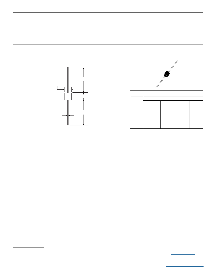
PACKAGE OUTLINE & DIMENSIONS
Outline & Dimensions: Rev 0 - 12/01, 06028
NOTES
1. Dimensions are exclusive of mold flash and metal burrs.
2. Suffix - LF = Lead-Free, Pure-Tin Plating, i.e.,
15KPA90A-LF.
A
B
C
D
E
-
9.10
-
1.30 DIA
9.10
1.00
0.34
1.00
0.048 DIA
0.34
-
0.36
-
0.052 DIA
0.36
24.5
8.60
24.5
1.20 DIA
8.60
DIM
MIN
MAX
MIN
MAX
MILLIMETERS
INCHES
PACKAGE DIMENSIONS
PACKAGE OUTLINE
AXIAL LEAD
E
A
B
C
D
COPYRIGHT © ProTek Devices 2005
SPECIFICATIONS: ProTek reserves the right to change the electrical and or mechanical characteristics described herein without notice (except JEDEC).
DESIGN CHANGES: ProTek reserves the right to discontinue product lines without notice, and that the final judgement concerning selection and
specifications is the buyer's and that in furnishing engineering and technical assistance, ProTek assumes no responsibility with respect to the selection or
specifications of such products.
ProTek Devices
2929 South Fair Lane, Tempe, AZ 85282
Tel: 602-431-8101 Fax: 602-431-2288
E-Mail:
sales@protekdevices.com
Web Site:
www.protekdevices.com