 | –≠–ª–µ–∫—Ç—Ä–æ–Ω–Ω—ã–π –∫–æ–º–ø–æ–Ω–µ–Ω—Ç: EM6D100L | –°–∫–∞—á–∞—Ç—å:  PDF PDF  ZIP ZIP |

EM6D-100L
1
05238.R3 1/06
www.protekdevices.com
EMI FILTER/TVS ARRAY
Only One Name Means ProTek'TionTM
APPLICATIONS
Cellular Phones
Color LCD Display Panel
Notebooks
Personal Digital Assistant (PDA)
Ground Positioning System (GPS)
SMART Cards
IEC COMPATIBILITY (EN61000-4)
61000-4-2 (ESD): Air - 15kV, Contact - 8kV
61000-4-4 (EFT): 40A - 5/50ns
FEATURES
ESD Protection > 25 kilovolts
EMI Filtering/TVS Low Pass Filters
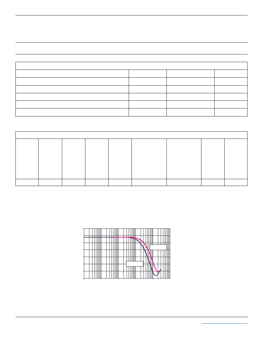
> 25db Attenuation from 800MHz to 3GHz
Protects Up to Six(6) Data Lines
RoHS Compliant in Lead-Free Versions
MECHANICAL CHARACTERISTICS
DFN-12 Package
Available in Tin-Lead or Lead-Free Pure-Tin Plating(Annealed)
Solder Reflow Temperature:
Tin-Lead - Sn/Pb, 85/15: 240-245∞C
Pure-Tin - Sn, 100: 260-270∞C
Flammability rating UL 94V-0
Device Marking: Marking Code
8mm Tape and Reel Per EIA Standard 481
05238
DFN-12
PIN CONFIGURATION
100 Ohm
10pF
10pF
I/On
GND
I/On
For Each Line
GND
1
2
3
4
5
6
12 11 10 9
8
7
BOTTOM VIEW
Note: I/O connected from pins 1-12, 2-11, 3-10, 4-9, 5-8 and 6-7.
2
www.protekdevices.com
05238.R3 1/06
EM6D-100L
DEVICE CHARACTERISTICS
ELECTRICAL CHARACTERISTICS PER LINE @ 25∞C Unless Otherwise Specified
25
TYPICAL
CAPACITANCE
PER LINE
(See Note 1)
@2.5V, 1MHz
C
pF
150
20
CUT-OFF
FREQUENCY
(50 OHMS I/O)
ZERO BIAS
f c
MHz
Note 1: 32pF @ 0V, 1MHz, ±20% tolerance.
0.8
TYPICAL
FORWARD
VOLTAGE
@10mA
V
F
VOLTS
MAXIMUM
REVERSE
LEAKAGE
CURRENT
@ 3V
I
D
µA
0.1
6.0
5.0
M6D 10L
EM6D-100L
PART
NUMBER
DEVICE
MARKING
RATED
STAND-OFF
VOLTAGE
V
WM
VOLTS
MINIMUM
BREAKDOWN
VOLTAGE
@ 1mA
V
(BR)
VOLTS
MINIMUM
ATTENUATION
@
800-3000 MHz
dB
-35
-30
-25
-20
-15
-10
-5
0
0.1
1
10
100
1000
10000
FIGURE 1
INSERTION LOSS
Gain (dB)
Frequency (MHz)
0 Volts
2.5 Volts
MAXIMUM RATINGS @ 25∞C Unless Otherwise Specified
Operating Temperature
SYMBOL
VALUE
-55∞C to 150∞C
∞C
∞C
-40∞C to 85∞C
UNITS
T
J
T
STG
PARAMETER
Storage Temperature
DC Power Per Resistor
mW
400
P
Typical Resistance @ ± 20%
OHMS
100
R
Soldering Temperature for 10 seconds
∞C
265∞C
T
L
3
www.protekdevices.com
05238.R3 1/06
EM6D-100L
GRAPHS
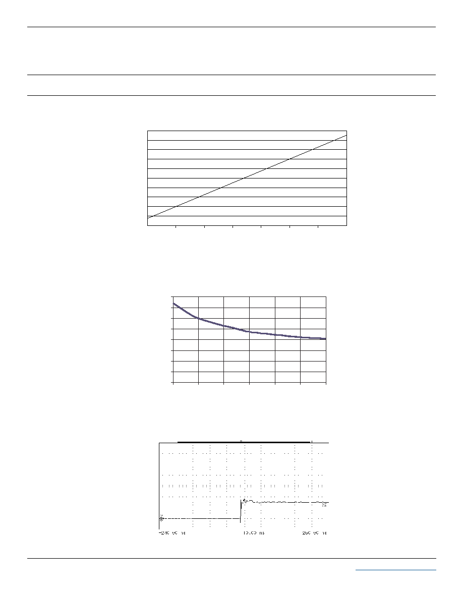
FIGURE 1
RESISTANCE VS TEMPERATURE
(Normalized to Resistance at 25∞C)
Temperature ∞C
0.900
Normalized Resistance
1.100
1.060
1.020
0.940
0.980
-40 -20 0 20 40 60 80 100
FIGURE 4
OVERSHOOT & CLAMPING VOLTAGE (through the filter)
ESD Test Pulse: +15 kilovolt, 1/30ns (waveform)
5 Volts per Division
-5
5
15
25
35
0
0.2
0.4
0.6
0.8
1
1.2
1.4
1.6
0
1
2
3
4
5
6
V
R
- Reverse Voltage - Volts
C
j
- Capacitance (Normalized)
FIGURE 3
CAPACITANCE VS REVERSE VOLTAGE
(Normalized to Capacitance at 2.5V DC & 25∞C)

4
www.protekdevices.com
05238.R3 1/06
EM6D-100L
PACKAGE OUTLINE & DIMENSIONS
COPYRIGHT © ProTek Devices 2005
SPECIFICATIONS: ProTek reserves the right to change the electrical and or mechanical characteristics described herein without notice (except JEDEC).
DESIGN CHANGES: ProTek reserves the right to discontinue product lines without notice, and that the final judgement concerning selection and
specifications is the buyer's and that in furnishing engineering and technical assistance, ProTek assumes no responsibility with respect to the selection or
specifications of such products.
ProTek Devices
2929 South Fair Lane, Tempe, AZ 85282
Tel: 602-431-8101 Fax: 602-431-2288
E-Mail:
sales@protekdevices.com
Web Site:
www.protekdevices.com
TAPE & REEL ORDERING NOMENCLATURE
1. Surface mount product is taped and reeled in
accordance with EIA 481.
2. Suffix-T7 = 7 Inch Reel - 5,000 pieces per 8mm
tape, i.e.,
EM6D-100L-T7.
3. Suffix-T13 = 13 Inch Reel - 15,000 pieces per 8mm
tape, i.e.,
EM6D-100L-T13.
4. Suffix- LF = Lead-Free, Pure Tin Plating,
i.e., EM6D-100L-LF-T7.
Outline & Dimensions: Rev 1 - 9/05, 06058
PACKAGE OUTLINE
A
A1
A3
b
D
E
E2
E3
E4
e
L
0.77
0.00
0.178
0.20
2.95
1.35
0.30
1.98
2.08
0.46
0.20
DIM
MILLIMETERS
INCHES
PACKAGE DIMENSIONS
NOTES:
1. Controlling dimensions in millimeters
2. Dimension b applies to terminal and is measured
between 0.25 and 0.30mm from terminal.
3. Coplanarity applies to the exposed pad as well as
the terminals.
MIN
MAX
MIN
MAX
0.030
0.00
0.007
0.008
0.116
0.053
0.012
0.078
0.082
0.018
0.008
0.033
0.002
0.009
0.012
0.122
0.057
0.016
0.088
0.092
0.022
0.011
0.84
0.05
0.228
0.30
3.10
1.45
0.40
2.24
2.34
0.56
0.28
D
E
A3
A
A3
A1
Pin 1 Reference
TOP VIEW
SIDE VIEW
e
L
E2
E3
E4
6
7
1
12
b
BOTTOM VIEW
Top cover tape
K0
t
D
P0
P2
10 Pitches Cumulative
Tolerance on Tape. ± 0.2
A0
B0
P
E
F
W
User Direction of Feed
Pin 1
Indicated
by Dot
Tape & Reel Specifications (Dimensions in millimeters)
D
E
P0
tmax
F
P2
W
1.50 ± 0.10 1.75 ± 0.10 3.50 ± 0.05 8.00 ±0.30 4.00 ±0.10 2.00 ±0.05
P
4.00 ±0.10
0.25
A0
B0
K0
Reel Dia.
Tape Width
178mm (7")/330mm(13")
8mm
1.60± 0.10
3.25± 0.10 0.95 ± 0.10