VSIP
ģ
SERIES A & B
1
05015.R4 8/03
www.protekdevices.com
VSIP
ģ
TVS ARRAY
Only One Name Means ProTek'TionTM
APPLICATIONS
RS-232 and RS-423 Data Lines
Telecommunications T/R Protection: ISDN, ADSL, V.34/V.90, HDLC, T1/E1 & T3/E3
Low & High Speed Data Lines: Ethernet, Token Ring, USB & FireWire
I/O Port Protection
IEC COMPATIBILITY (EN61000-4)
61000-4-2 (ESD): Air - 15kV, Contact - 8kV
61000-4-4 (EFT): 40A - 5/50ns
61000-4-5 (Surge): 24A, 8/20Ķs - Level 2(Line-Gnd) & Level 3(Line-Line)
FEATURES
Series A: 800 Watts Peak Pulse Power per Line (tp=8/20Ķs)
Series B: 3,400 Watts Peak Pulse Power per Line (tp=8/20Ķs)
ESD Protection > 40 kilovolts
High Surge Capability & Low Capacitance Option
Protects 8 to 9 Bidirectional Data Lines
Available in 5 Voltages Types Ranging from 5V to 24V
MECHANICAL CHARACTERISTICS
Molded Plastic VSIP
ģ
Package
Weight 1.5 grams (Approximate)
Flammability rating UL 94V-0
Marking: Logo, Part Number, Date Code & Pin One Defined By Dot on Top of Package
05015
PIN CONFIGURATIONS
VSIP
ģ
UNIDIRECTIONAL
BIDIRECTIONAL
LOW CAPACTIANCE
ISOLATED
LOW CAPACITANCE
2
www.protekdevices.com
05015.R4 8/03
VSIP
ģ
SERIES A & B
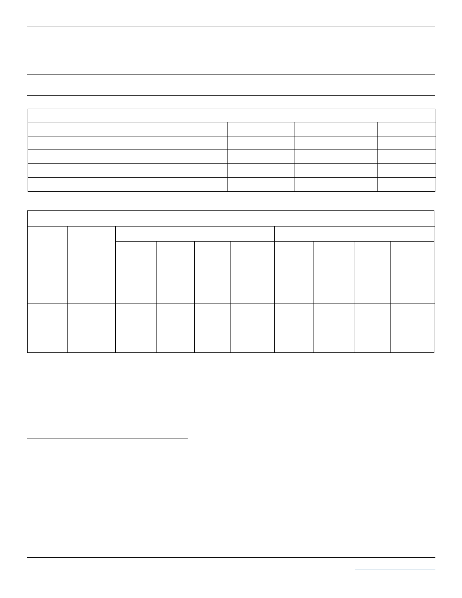
DEVICE CHARACTERISTICS
MAXIMUM RATINGS @ 25įC Unless Otherwise Specified
SYMBOL
VALUE
UNITS
PARAMETER
Operating Temperature
-55
į
C to 150
į
C
įC
įC
-55
į
C to 150
į
C
T
J
T
STG
Storage Temperature
Series A Peak Pulse Power (t
p
= 8/20Ķs) - See Figure 1
P
PP
800
Watts
Series B Peak Pulse Power (t
p
= 8/20Ķs) - See Figure 1
P
PP
3400
Watts
ELECTRICAL CHARACTERISTICS PER LINE @ 25įC Unless Otherwise Specified
RATED
STAND-OFF
VOLTAGE
(See Notes 1-3)
V
WM
VOLTS
MINIMUM
BREAKDOWN
VOLTAGE
@ 1mA
V
(BR)
VOLTS
MAXIMUM
CLAMPING
VOLTAGE
(See Fig. 2)
@ I
P
= 1A
V
C
VOLTS
MAXIMUM
CLAMPING
VOLTAGE
(See Fig. 2)
@ I
P
= 10A
V
C
VOLTS
MAXIMUM
LEAKAGE
CURRENT
@V
WM
I
D
AMPS
MAXIMUM
PEAK PULSE
CURRENT
(See Fig. 2)
I
PP
AMPS
MAXIMUM
CLAMPING
VOLTAGE
(See Fig. 2)
@ I
P
= 1A
V
C
VOLTS
MAXIMUM
CLAMPING
VOLTAGE
(See Fig. 2)
@ I
P
= 10A
V
C
VOLTS
MAXIMUM
LEAKAGE
CURRENT
@V
WM
I
D
AMPS
MAXIMUM
PEAK PULSE
CURRENT
(See Fig. 2)
I
PP
AMPS
SERIES A
SERIES B
9.8
13.4
19.5
24.4
39.1
12.5
16.6
22.7
28.5
45.6
100
10
1
1
1
45
40
34
27
22
8.6
10.9
17.0
21.4
34.2
9.1
12.0
18.8
23.6
37.8
300
200
2
2
2
300
258
184
147
93
6.0
8.5
13.3
16.7
26.7
5.0
8.0
12.0
15.0
24.0
Note 1:
For voltage types not shown on the product data sheet, consult the factory.
Note 2:
The low capacitance configuration values for each bidirectional line pair is as follows:
Series "A" C = 25pF
Series "B" C = 100pF
Note 3:
Forward voltage (
unidirectional configurations only):
Series "A": V
F
= 1.5V @ 200mA
Series "B": V
F
= 1.5V 200mA
STANDARD PRODUCT ORDERING BY PART NUMBER
Unidirectional - VS10Pxx (A Series), VSB10Pxx (B Series)
Bidirectional - VS10PxxC (A Series), VSB10PxxC(B Series)
Low Capacitance - VS10PxxLC (A Series), VSB10PxxLC (B Series)
Isolated Low Capacitance- VS10PxxLCI (A Series), VSB10PxxLCI (B Series)
xx = Selected Voltage
3
www.protekdevices.com
05015.R4 8/03
VSIP
ģ
SERIES A & B
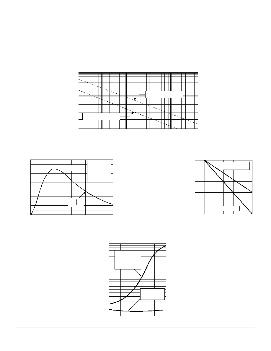
GRAPHS
FIGURE 1
PEAK PULSE POWER VS PULSE TIME
100
1,000
10,000
100,000
P
PP
- Peak Pulse Power - Watts
0.01 1 10 100 1,000 10,000
t
d
- Pulse Duration - Ķs
3,400W, 8/20Ķs Waveform
800W, 8/20Ķs Waveform
0 25 50 75 100 125 150
T
L
- Lead Temperature - įC
20
40
60
80
100
% Of Rated Power
Peak Pulse Power
8/20Ķs
Average Power
FIGURE 3
POWER DERATING CURVE
0
0 5 10 15 20 25 30
t - Time - Ķs
0
20
40
60
80
100
120
I
PP
- Peak Pulse Current - % of I
PP
TEST
WAVEFORM
PARAMETERS
t
f
= 8Ķs
t
d
= 20Ķs
t
f
Peak Value I
PP
e
-t
t
d
= t
I
PP
/2
FIGURE 2
PULSE WAVE FORM
1000
100
10
0 1 2 3 4 5
Industry
Standard Low
Capacitance TVS
Protector
Low Capacitance
VS10PxxLC
V
(OP)
- Circuit Opeerating - Volts
C - TVS Capacitance - pF
FIGURE 4
TYPICAL LOW CAPACITANCE CURVE
4
www.protekdevices.com
05015.R4 8/03
VSIP
ģ
SERIES A & B
COPYRIGHT © ProTek Devices 2003
SPECIFICATIONS: ProTek reserves the right to change the electrical and or mechanical
characteristics described herein without notice (except JEDEC).
DESIGN CHANGES: ProTek reserves the right to discontinue product lines without notice, and that
the final judgement concerning selection and specifications is the buyer's and that in furnishing
engineering and technical assistance, ProTek assumes no responsibility with respect to the
selection or specifications of such products.
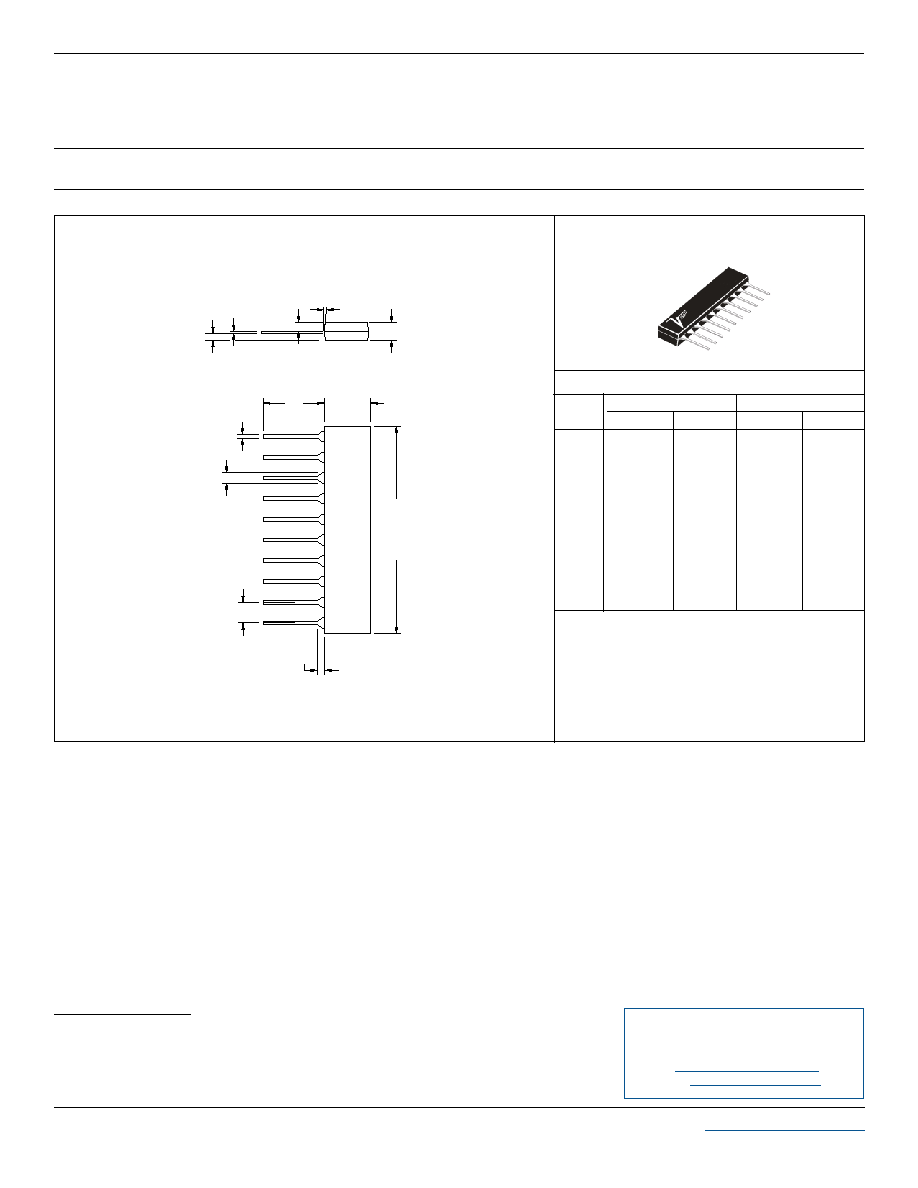
PACKAGE OUTLINE & DIMENSIONS
ProTek Devices
2929 South Fair Lane, Tempe, AZ 85282
Tel: 602-431-8101 Fax: 602-431-2288
E-Mail:
sales@protekdevices.com
Web Site:
www.protekdevices.com
Outline & Dimensions: Rev 1 - 11/01, 06016
BULK ORDERING NOMENCLATURE
1. Product Shipped in Tubes of 18 pcs per Tube.
PACKAGE OUTLINE
A
B
C
D
E
F
G
H
I
J
K
L
26.01
6.45
6.02
0.508
1.57
2.59
1.02
3.40
7į TYP
1.57
0.30
1.57
1.016
0.246
0.233
0.016
0.058
0.098
0.015
0.126
7į TYP
0.058
0.008
0.058
1.024
0.254
0.237
0.020
0.062
0.102
0.040
0.134
7į TYP
0.062
0.012
0.062
25.81
6.25
5.92
0.406
1.47
2.49
0.38
3.20
7į TYP
1.47
0.20
1.47
DIM
MIN
MAX
MIN
MAX
MILLIMETERS
INCHES
VSIP DIMENSIONS
VSIP
ģ
PACKAGE
NOTES
1. Dimensions are exclusive of mold flash and metal burrs.
G
F
E
D
C
B
A
H
I
J
K
L