
T ECH NITROL
PART NO.
TAP D ELA YS (ns)
ALL TAPS
T
D
D
1
T
D
D
2
T
D
D
3
T
D
D
4
T
D
D
5
T
RO
RO
T
FO
FO
CT TLDL025
5.0
10.0
15.0
20.0
25.0
2.0
2.0
CT TLDL050
10.0
20.0
30.0
40.0
50.0
2.0
2.0
CT TLDL075
15.0
30.0
45.0
60.0
75.0
2.0
2.0
CT TLDL100
20.0
40.0
60.0
80.0
100.0
2.0
5.0
CT TLDL125
25.0
50.0
75.0
100.0
125.0
2.0
5.0
CT TLDL150
30.0
60.0
90.0
120.0
150.0
2.0
6.0
CT TLDL200
40.0
80.0
120.0
160.0
200.0
2.0
7.0
High-Performance Surface-Mount
TTL Delay Lines
n
Five equal taps in 20% increments of total delay.
n
Lumped constant, active series.
n
Transfer-molded packaging for highest reliability.
n
Designed for leading edge timing. Trailing edge
timing available.
n
Supports Schottky TTL, FAST, and FACT logics.
n
Fanout 1 -- 20 loads; logic 0 -- 10 loads.
n
Temperature coefficient +2 ns or +4% (whichever is
greater) at maximum delay, 0 to 70oC.
TWO PEARL BUCK COURT
l
BRISTOL, PA 19007-6812
l
TEL 215-781-6400
l
FAX 215-781-6403
l
www.pulsespecialty.com
n
Military models with temperature range -55 to
+125
o
C and ceramic package IC to meet MIL-STD-
883C, but not screened to that specification, add
suffix "M" to part number.
n
Military models as above, but with ceramic package
IC screened to MIL-STD 883C and 38510, add
suffix "MX" to part number.
n
Military models as "MX" above, but with in-house
burn-in and thermal shock, add suffix "MY".
For TTL delay lines qualified
to MIL-D-83532, refer to PSC
information sheet entitled
"QPL Active Delay Lines."
CTTLDL,
BJTTLDL,
GBTTLDL,
BTTLDL
Delay Characteristics measured at Vcc = 5.0V, 25
o
C, no load.
Delay Tolerance +2 ns or 5%, whichever is greater.
Rise time measured @ 0.8V to 2.0V levels.
For minimum input pulse width -- contact factory.
LOW PROFILE SURFACE-MOUNT 5-TAP TTL DELAY LINES
O.175"
MAX
HEIGHT
SCHEMATIC
MECHANICAL OUTLINE
Notes
n
Pin numbers shown are for reference only
and are not necessarily marked on unit.
n
Lead material is electro tin plated
(alloy 42) or solder dipped.
n
All specifications are subject to change
without notice.
TWO PEARL BUCK COURT
l
BRISTOL, PA 19007-6812
l
TEL 215-781-6400
l
FAX 215-781-6403
l
www.pulsespecialty.com
CTTLDL,
BJTTLDL,
GBTTLDL,
BTTLDL
Delay Characteristics measured at Vcc = 5.0V, 25
o
C, no load.
Delay Tolerance +2 ns or 5%, whichever is greater.
Rise time measured @ 0.8V to 2.0V levels.
For minimum input pulse width -- contact factory.
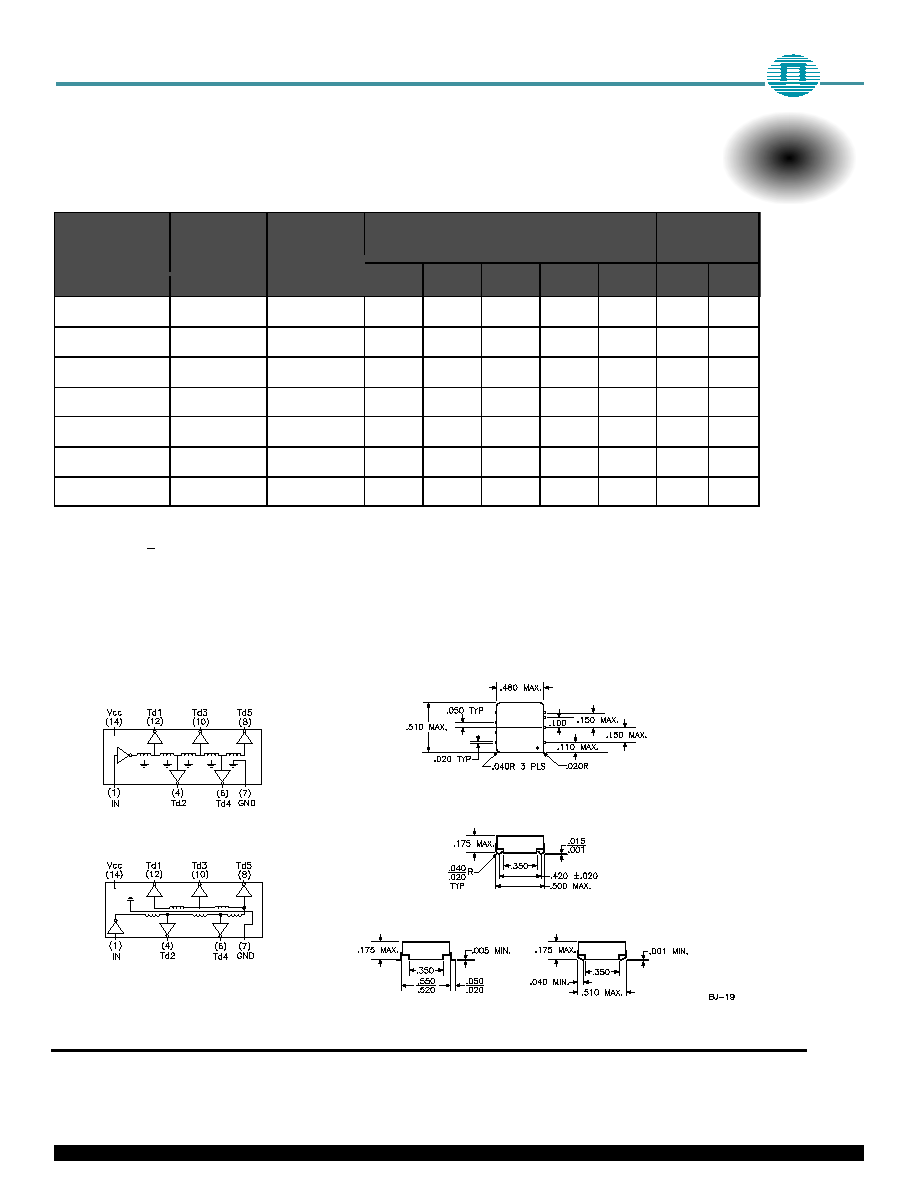
SURFACE-MOUNT 5-TAP TTL DELAY LINES -- 1/2" SQ.
T ECHNITR OL
PAR T NO.
PART NO.
PA RT NO.
TAP D ELAYS (ns)
ALL TAPS
( Max.)
T
D
D
1
T
D
D
2
T
D
D
3
T
D
D
4
T
D
D
5
T
RO
RO
T
FO
FO
BJT TLDL025
GBTT LDL025
BT TTLDL25
5.0
10.0
15.0
20.0
25.0
2.0
2.0
BJT TLDL050
GBTT LDL050
BT TTLDL50
10.0
20.0
30.0
40.0
50.0
2.0
2.0
BJT TLDL075
GBTT LDL075
BT TTLDL75
15.0
30.0
45.0
60.0
75.0
2.0
2.0
BJT TLDL100
GBTT LDL100
BTTTLDL100
20.0
40.0
60.0
80.0
100.0
2.0
5.0
BJT TLDL125
GBTT LDL125
BTTTLDL125
25.0
50.0
75.0
100.0
125.0
2.0
6.0
BJT TLDL150
GBTT LDL150
BTTTLDL150
30.0
60.0
90.0
120.0
150.0
2.0
7.0
BJT TLDL200
GBTT LDL200
BTTTLDL200
40.0
80.0
120.0
160.0
200.0
2.0
8.0
MECHANICAL OUTLINES
SCHEMATICS
BJTTLDL
GBTTLDL and BTTLDL
J-Lead
BJTTLDL
C-Lead
BTTLDL
Gull Wing
GBTTLDL
Notes
n
Pin numbers shown are for reference only
and are not necessarily marked on unit.
n
Lead material is electro tin plated
(alloy 42) or solder dipped.
n
All specifications are subject to change
without notice.