
QPL Active Delay Lines (TTL)
n
Active 5 tap, 14-pin DIP delay lines qualified to MIL-D-83532.
n
Established reliability assured through a fully approved program in
accordance with MIL-STD-790.*
n
Standard total delay values ranging from 25 to 500 ns and tap delay
values from 5 to 100 ns.
n
Other military part numbers with non-standard delay values
available upon request.
n
QPL JAN I.C.'s (in accordance with MIL-M-38510) incorporated
in all active delay lines.
n
All units transfer molded for maximum reliability.
n
Pulse Specialty Components - the first delay line supplier to be QPL'd.
*Reliability Assurance Program for Electronic Parts Specifications
TWO PEARL BUCK COURT
l
BRISTOL, PA 19007-6812
l
TEL 215-781-6400
l
FAX 215-781-6403
l
www.pulsespecialty.com
MILITA RY
PAR T N O.
T ECHNIT ROL
PART NO.
TAP D ELA YS (ns)
T
R
R
+*
T
D
D
1
T
D
D
2
T
D
D
3
T
D
D
4
T
D
D
5
M83532/02A001A
TTLDL0257JY
5.0
10.0
15.0
20.0
25.0
4.0
M83532/02A006A
TTLDL0507JY
10.0
20.0
30.0
40.0
50.0
4.0
M83532/02A011A
TTLDL0757JY
15.0
30.0
45.0
60.0
75.0
4.0
M83532/02A014A
TTLDL1007JY
20.0
40.0
60.0
80.0
100.0
4.0
M83532/02A015A
TTLDL1257JY
25.0
50.0
75.0
100.0
125.0
4.0
M83532/02A016A
TTLDL1507JY
30.0
60.0
90.0
120.0
150.0
4.0
M83532/02A018A
TTLDL2007JY
40.0
80.0
120.0
160.0
200.0
4.0
M83532/02A020A
TTLDL2507JY
50.0
100.0
150.0
200.0
250.0
4.0
M83532/02A026A
TTLDL5007JY
100.0
200.0
300.0
400.0
500.0
5.0
ACTIVE MIL-D-83532 QPL DELAY LINES (TTL LOGIC)
NOTE: Additional slash numbers from 02A001A through 02A029A available upon request.
*Measured @ V
cc
= 5.0V, 25
o
C, with 50pf load to ground and 500 ohms to V
cc
First QPL'd
delay lines.
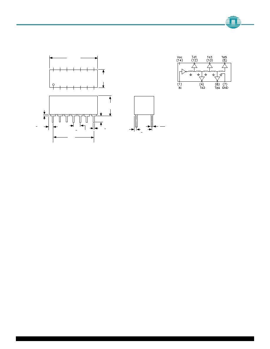
.810 MAX
.400
MAX
.360
MAX
.125 MIN
.200 MAX
.020 + .002
.100 + .010
NONCUMULATIVE
.600
.105 + .015
4 PLACES
.015
MIN
STANDOFF
HEIGHT
1 2 3 4 5 6 7
14 13 12 11 10 9 8
.060
MAX.
.300
+.010
.007
.012
TWO PEARL BUCK COURT
l
BRISTOL, PA 19007-6812
l
TEL 215-781-6400
l
FAX 215-781-6403
l
www.pulsespecialty.com
SCHEMATIC
MECHANICAL OUTLINE
Notes
n
Only the pins specified in the schematics
are provided with each package.
n
Pin numbers shown are for reference only
and are not necessarily marked on unit.
n
Lead material is electro tin plated
(alloy 42) or solder dipped.
n
All specifications are subject to change
without notice.