Copperhead
TM
Series
Fibre Channel transceiver
line interface module
Fiber speed data and communications
over 100+ meters of copper
Features
High performance, low cost alternative to completely fiber systems
Enhanced distance and signal clarity with complete inter-operability per ANSI X3T11,
FC-PH (FC-0 Rev 9.1)
Small, discrete passive design incorporates equalizer, transformers, and filters for
"short haul" applications; industrial temp -40∞C to +85∞C (-55∞C to +125∞C available)
Compact active models for "long haul" applications; -40∞C to +85∞C and -55∞ to +125∞
Low EMI emissions; designed for FCC Class B compliance and use over shielded
twisted pair cable with high radiated electromagnetic susceptibility - 10 V/m
Low transmit/receive jitter
Small footprint for surface mounting
Low power dissipation; 450 mW typical
ECL logic interface - directly compatible with proposed standards
Applications
Fibre Channel
HDTV
Gigabit Ethernet
SMPTE
SONET
IEEE 1394B
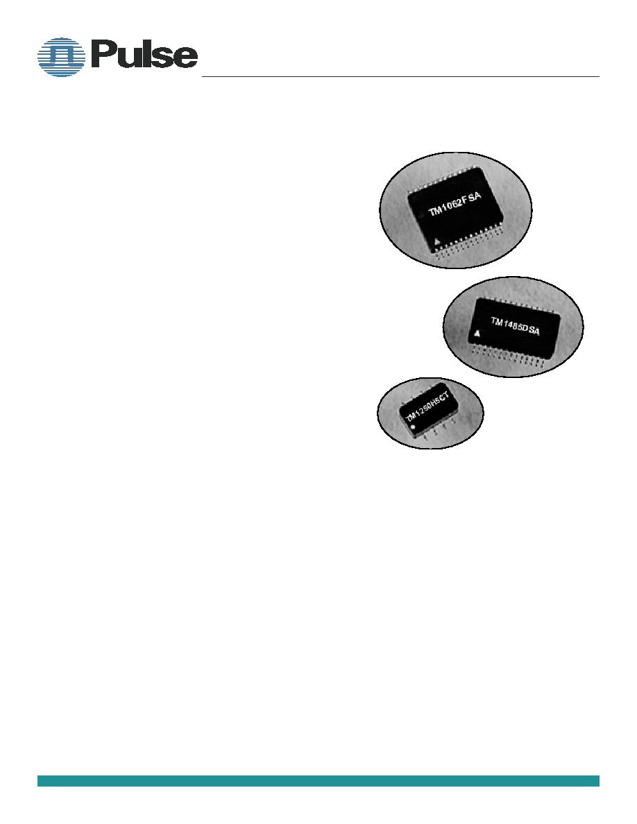
Designed to be inter-operable with existing ECL fiber transceiver
drivers, Copperhead
TM
fibre channel copper transceiver line
interface modules drive high frequency (fiber speed) signals
over copper media. Models TM133 thru TM1062 are designed to
deliver fibre channel capabilities to the workstation over shielded
twisted pair (STP), twinax, mini coax, and video coaxial cable.
Model TM1250 provides communications for short haul Gigabit
Ethernet applications, typically over twinax or coaxial cable.
Model TM1485 provides communications for SMPTE, also typi-
cally over twinax or coax cable. All Copperhead
TM
fibre channel
copper transceiver line interface modules are supplied as sur-
face mount gull wing packages.
TWO PEARL BUCK COURT
BRISTOL, PA 19007-6812
TEL 215-781-6400
FAX 215-781-6403
www.pulsespecialty.com
Specialty Components

Technical description
Copperhead
TM
fibre channel transceiver line interface modules (LIM) take differential
ECL level NRZ data signal from the available fibre channel (or Gigabit Ethernet) silicon.
The signal is then converted to drive level, pre-conditioned with an output filter, and
transmitted over the cable through an interfacing wideband pulse transformer.
The transformer converts the signal to current and voltage levels, with exceptionally
low transmit jitter, suitable for transmission on STP, twinax or coaxial cable. The trans-
ceiver matches the impedance of both the ECL circuit and the cable plant, providing a
resultant output signal with minimum jitter and return loss.
The receiver portion of the transceiver LIM takes the signal from the media cable
and equalizes it by using a unique wideband pulse transformer and circuitry. This initi-
ates the conversion process of reducing the composite signal to ECL level NRZ for the
next level fibre channel silicon.
Benefits of transformer coupling
The pulse transformers used in Copperhead
TM
transceiver LIMs provide high isolation
and optimum damping of transients. They also eliminate DC components in the signal
and provide common mode signal rejection. The transformer is also used to match the
load to the source and provide maximum power transfer, and also to prevent reflections
from transmission line effects.
(Figure 1) Actual oscilloscope tracing of 1.0625
Gb/s unequalized input to receiver pins 13 and
14 after transmission over 30 meters of twinax
cable.
(Figure 2) Tracing of the same signal after
equalization. Receiver output measured at pins
2 and 3.
BEFORE
(unequalized)
AFTER
(equalized for Fibre Channel)
TWO PEARL BUCK COURT
BRISTOL, PA 19007-6812
TEL 215-781-6400
FAX 215-781-6403
www.pulsespecialty.com
Fibre Channel Module -- 2
P
ULSE
S
PECIALTY
C
OMPONENTS

EMC Immunity and Radiated Emissions Tests
Radiated Emissions, FCC Class B, 6 dB margin
IEC 1000-4-2 ESD Test Method
Performance Criteria B, Level 2
IEC 1000-4-3 Radiated Immunity
Performance Criteria A, Level 3 (10V/m)
IEC 10004-4 EFT Test Method
Performance Criteria B, Level 3 (at I/O port)
Criteria A: The system shall continue to operate normally. The EUT shall be deemed to have passed the immunity tests if no bit
errors occur when receiving data over the cable. Changes of state, reset condition, unrecoverable jab condition,
blocked network, or loss of packets is unacceptable.
Criteria B: The system shall operate normally with no data errors through the loop after the test. During the test, data errors,
aborted frames and collisions are acceptable. No change of operating state such as system reset or unrecoverable
condition is permitted during or after the test.
Product Qualification Test Outline
V. Subgroup V (6 pieces)
Thermal shock
Per MIL-STD-202, Method 107, Condition A-1, except
temperature range shall be -20∞ C to +125∞ C, 25 cycles
Vibration
Per MIL-STD-202, Method 204D, Condition D, 20G
peak acceleration, 10 Hz to 2 KHz and return to 10 Hz
traversed in 6 minutes
Shock
Per MIL-STD-202, Method 213B, Condition J, 30G,
11msec shock, 3 shocks in each direction along
mutually perpendicular axes
VI. Subgroup VI (6 pieces)
Life Test
Per MIL-STD-202, Method 108, 1000 hours at a
temperature of 75∞ C
VII. Subgroup VII (8 pieces)
Humidity Test
Humidity test @ 40∞ C, and 90% humidity (4 pieces)
VIII. Subgroup VIII (6 pieces)
Electrostatic Discharge, ESD Classification
The ESD classification to be derived from ESD
testing per IEC801-2, EN50082-1, Criteria B
NOTE: There shall be 0 (zero) rejects allowable for
each of the subgroups.
I. Subgroup I (all devices - 40 pieces)
Electrical tests at 25
∞
Receiver (R
x
) tests
- Jitter (total peak-to-peak)
Transmit (T
X
) tests
- CMI Mask Test (rise time, fall time, and amplitude)
- Jitter (total peak-to-peak)
Total power supply current
II. Subgroup II (4 pieces)
External visual inspection
Resistance to solvents per MIL-STD-202, Method 215H
- 1 part isopropyl alcohol, 3 parts mineral spirits
- Trichloroethane
- Terpene defluxer with a minimum of 90% d-limonene
and 10% surfactant
- 42 parts water, 1 part propylene glycol monomethyl
ether, 1 part monoethanolamine
Terminal strength per MIL-STD-883, Method 2004.5
- Lead tension
III. Subgroup III (4 pieces)
Solderability
Per MIL-STD-202, Method 208, with a 4-hour
steam age
IV. Subgroup IV (6 pieces)
Resistance to soldering heat
Hand solder (2 pieces), solder dip temperature of 430
±5∞ C for 3 seconds maximum
Vapor phase reflow (4 pieces) for a period of 60
seconds at a temperature of 215 +5/-0∞ C
TWO PEARL BUCK COURT
BRISTOL, PA 19007-6812
TEL 215-781-6400
FAX 215-781-6403
www.pulsespecialty.com
Fibre Channel Module -- 3
P
ULSE
S
PECIALTY
C
OMPONENTS

JITTER PARAMETER
TOTAL JITTER
Dat a rate
1 33 M b
2 66 Mb
53 1 Mb
1 .06 2 G b
UNIT
Tra nsmit in (PHY )
1.2 04
0 .602
0.3 77
0 .188
ns
Tra nsmit out (PHY+ Tra nsmitt er)
1.3 56
0 .678
0.4 14
0 .207
ns
Receive out (PHY+ T ransmit ter+ Cable+ Rec eiver)
6 .0
2.6 4
1 .32
0 .658
ns
Important: This is a hybrid device and is rated for 220
o
C max for 60 seconds.
Contact factory for recommended solder reflow profile.
PARAMETER
SYM
MIN
MAX
UNIT
St orage t emperature
T
S
-55
+1 50
∞C
Ope rating t empe rature ambient Act ive
1
Passive
T
A
T
A
-40
-55
+ 85
+1 25
∞C
∞C
Power supply volt age ( M ECL, PEC L or LV PECL )
V
C C
-6.0
6.0
V
Power supply c urre nt
2
I
C
-
95
mA
Power dissipation (total)
P
D
-
500
mW
Out put c urre nt
I
O
-
100
mA
Dat a input voltage
V
I
0
V
C C
+0.5
V
Diff erential input volta ge
V
D
-
2.40
V
Component body t emperature/time
-
-
220/60
∞C/s
Thermal Re sistance (case to junction)
(t het a)jc
54
∞C/w
∞C
∞C
Table 2
Table 1
Absolute Maximum Ratings
System Jitter Budget
Note 1: Exception: for TM1062DSA1, -55
∞
to +125
∞
C
Note 2: Excluding external pull-down resistors
Copperhead
TM
fibre channel copper transceivers require less than 50% (worst case) of system jitter budget
Note: These numbers are currently under evaluation by a special Jitter Study Group in ANSI X3T11 and IEEE 802.3z.
TWO PEARL BUCK COURT
BRISTOL, PA 19007-6812
TEL 215-781-6400
FAX 215-781-6403
www.pulsespecialty.com
Fibre Channel Module -- 4
P
ULSE
S
PECIALTY
C
OMPONENTS

Table 3
Transmitter Electrical Characteristics
V
CC
= 3.14V to 5.25V
PARAMETER
SYM
MIN
TYPICAL
MAX
UNIT
Input da ta voltage Low
High
V
IL
V
IH
V
C C
-1.95
V
C C
-1.23
V
C C
-1.75
V
C C
-0.88
V
C C
-1.45
V
C C
-0.72
V
V
Input c urre nt Low
High
I
IL
I
IH
-15 0
-
-
-
-
150
uA
uA
Dat a rate ( NRZ Encoding)
DR
1 33
-
1 485
M b/s
Diff erential signal level
1
T MXX XXXSA1
(peak-peak) TM XXXX XSA
V
OT
1100
6 00
-
2 000
1 600
mV
mV
Out put rise and f all t ime
1
for TM 1062
(20-80% )
T
R
/T
F
-
-
300
ps
Re turn loss (0.1 to 0.5 of baud rate)
S
1 1
-12
-
-
dB
Total peak-peak tr ansmit jitt er (D
J
+R
J
)
12- TP-EL-S 133 Mb
25- TP-EL-S 2 66 Mb
50- TP-EL-S 5 31 Mb
100- T P-EL-S 106 2 Mb
1250 M b
1485 M b
T
PK- PK
-
-
-
-
500
250
125
6 2
750
376
188
94
ps
ps
ps
ps
Table 4
Receiver Electrical Characteristics V
CC
= 3.14V to 5.25V
Note 1: Differential signal level (V
OT
), rise time (T
R
) and overshoot (O
S
) shall be measured at the transmitter output
with 150 ohm differential termination as load. The data pattern for this test shall be a square wave of 0.1 bit rate.
PARAMETER
SYM
MIN
TYPICAL
MAX
UNIT
Out put dat a voltage Low
High
V
OL
V
OH
V
C C
-1.95
V
C C
-1.15
V
C C
-1.77
V
C C
-0.96
V
C C
-1.56
V
C C
-0.76
V
V
Dat a rate ( NRZ Encoding)
DR
13 3
-
14 85
M b/s
Input sensit ivity ( D2 1.5 idle patt ern)
-
15 0
-
-
mV
Input diff erential voltage
V
DIF F
-
-
2.40
V
Re turn loss (0.1 to 0.5 bit r ate) ST P
S
1 1
-15
-17
-
dB
Total peak-peak receive jitter 133 M b
26 6 Mb
53 1 Mb
1062 M b
1250 M b
1485 M b
T
PK- PK
-
-
-
-
0.350
0.350
0.240
0.120
1.5 00
0.9 00
0.6 50
0.4 00
ns
ns
ns
ns
TWO PEARL BUCK COURT
BRISTOL, PA 19007-6812
TEL 215-781-6400
FAX 215-781-6403
www.pulsespecialty.com
Fibre Channel Module -- 5
P
ULSE
S
PECIALTY
C
OMPONENTS