144-pin SDRAM SODIMMs
Preliminary Data Sheet
64MB, 128MB, 256MB, 512MB
Enhanced Memory Systems Inc., 1850 Ramtron Dr., Colo Spgs, CO 80921
2001 Enhanced Memory Systems. All rights reserved.
PHONE: (800) 545-DRAM; FAX: (719) 488-9095;
http://www.edram.com
The information contained herein is subject to change without notice.
Revision 1.0
Page 1 of 15
Features
∑
JEDEC Standard 144-pin PC133 SDRAM SODIMM
∑
Fast 5.4 ns Clock Access Time
∑
Supports CAS Latency = 2, 3
∑
On-board Serial Presence Detect (SPD)
∑
Unbuffered 144-pin SODIMM
∑
4K Refresh / 64ms (8K Refresh for 512MB DIMM)
∑
Single 3.3V
±
0.3V Power Supply
Description
The Enhanced Memory Systems 64MB, 128MB, 256MB,
and 512MB Small Outline DIMMs (1.05-inch height) are the
fastest SODIMMs available for notebook and embedded
system applications. This PC133 product provides the lowest
cost for both PC133 and PC100 sockets. The fast 5.4 ns
clock access time allows unbuffered operation at 133 MHz
for lower memory latency, and lower costs than registered
DIMMs.
The 64MB module is organized as 8Mx64, the 128MB
module is organized as 16Mx64, the 256MB module is
organized as 32Mx64, and the 512MB module is organized
as 64Mx64. Each module has a serial presence EEPROM,
which contains information on the module type, module
organization, component speed, and other attributes relevant
to the system controller.
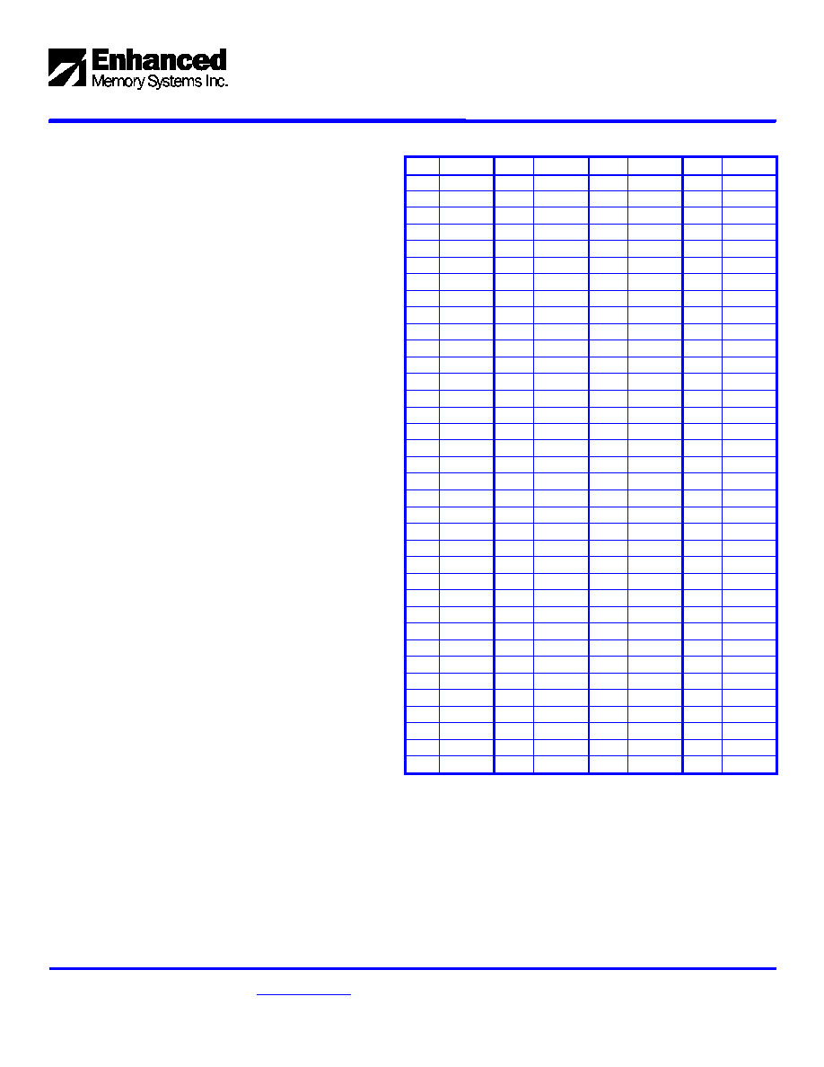
Pin Symbol Pin Symbol Pin Symbol Pin Symbol
1 Vss 37 DQ8 73 RSVD
109 Vss
2 Vss 38
DQ40
74 CK1 110 A9
3 DQ0 39 DQ9 75 Vss 111
A10/AP
4 DQ32 40 DQ41 76 Vss 112 NC
5 DQ1 41 DQ10 77 RSVD
113 Vdd
6 DQ33 42 DQ42 78 RSVD 114 Vdd
7 DQ2 43 DQ11 79 RSVD
115
DQMB2
8 DQ34 44 DQ43 80 RSVD 116
DQMB6
9 DQ3 45 Vdd 81 Vdd 117
DQMB3
10
DQ35 46 Vdd 82 Vdd 118
DQMB7
11 Vdd 47 DQ12 83 DQ16 119 Vss
12 Vdd 48 DQ44 84 DQ48 120 Vss
13 DQ4 49 DQ13 85 DQ17 121 DQ24
14 DQ36 50 DQ45 86 DQ49 122 DQ56
15 DQ5 51 DQ14 87 DQ18 123 DQ25
16 DQ37 52 DQ46 88 DQ50 124 DQ57
17 DQ6 53 DQ15 89 DQ19 125 DQ26
18 DQ38 54 DQ47 90 DQ51 126 DQ58
19 DQ7 55 Vss 91 Vss 127
DQ27
20
DQ39 56 Vss 92 Vss 128
DQ59
21 Vss 57 NC 93 DQ20
129 Vdd
22 Vss 58 RSVD 94 DQ52
130 Vdd
23 DQMB0 59 NC 95 DQ21 131 DQ28
24 DQMB4 60 RSVD 96 DQ53 132 DQ60
25 DQMB1 61 CK0 97 DQ22 133 DQ29
26
DQMB5
62 CKE0 98 DQ54 134 DQ61
27 Vdd 63 Vdd 99 DQ23
135
DQ30
28 Vdd 64 Vdd 100 DQ55 136 DQ62
29 A0
65 RAS# 101 Vdd 137 DQ31
30 A3
66 CAS# 102 Vdd 138 DQ63
31 A1 67 WE#
103 A6 139 Vss
32 A4 68 CKE1
104 A7 140 Vss
33 A2 69 S0# 105 A8 141 SDA
34 A5 70 A12 106 BA0 142 SCL
35 Vss 71 S1# 107 Vss 143 Vdd
36 Vss 72 NC 108 Vss 144 Vdd
144-pin SDRAM SODIMMs
64MB, 128MB, 256MB, 512MB
Preliminary Data Sheet
Enhanced Memory Systems Inc., 1850 Ramtron Dr., Colo Spgs, CO 80921
2001 Enhanced Memory Systems. All rights reserved.
PHONE: (800) 545-DRAM; FAX: (719) 488-9095;
http://www.edram.com
The information contained herein is subject to change without notice.
Page 2 of 15
Revision 1.0
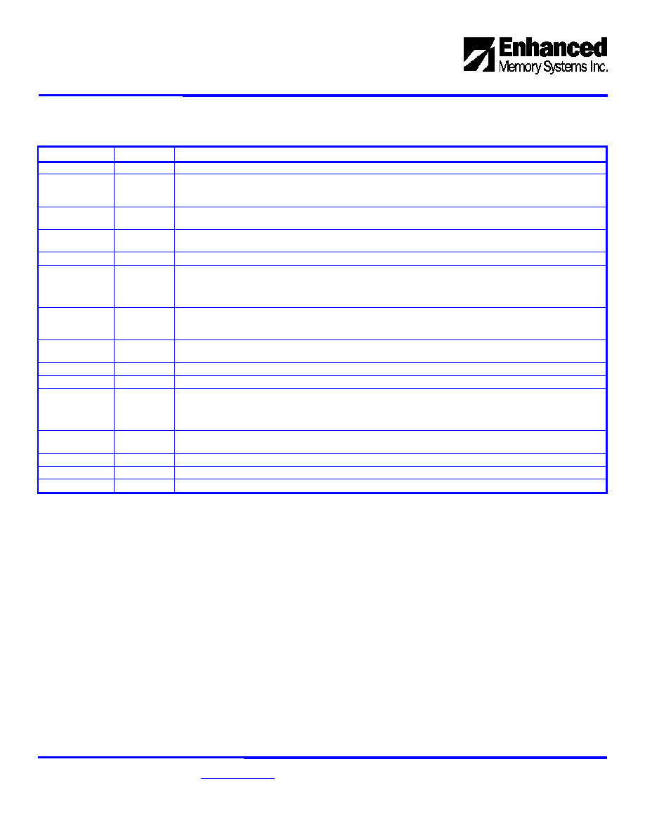
Pin Descriptions
Symbol Type
Function
CK(0:1) Input
Clocks: All SDRAM input signals are sampled on the positive edge of CK.
CKE(0:1) Input
Clock Enables: CKE activate (high) or deactivate (low) the CK signals. Deactivating the clock initiates the
Power-Down and Self-Refresh operations (all banks idle), or Clock Suspend operation. CKE is synchronous until
the device enters Power-Down and Self-Refresh modes where it is asynchronous until the mode is exited.
S(0:1)# Input
Chip Select: S# enables (low) or disables (high) the command decoder. When the command decoder is
disabled, new commands are ignored but previous operations continue.
RAS#, CAS#,
WE#
Input
Command Inputs: Sampled on the rising edge of CK, these inputs define the command to be executed.
BA(0:1)
Input
Bank Addresses: These inputs define to which of the 4 banks a given command is being applied.
A(0:12) Input
Address Inputs: A0-A12 define the row address during the Bank Activate command. A0-A9 define the column
address during Read and Write commands. A10/AP invokes the Auto-precharge operation. During manual
Precharge commands, A10/AP low specifies a single bank precharge while A10/AP high precharges all banks.
The address inputs are also used to program the Mode Register.
DQ(0:63)
Input/
Output
Data I/O: Data bus inputs and outputs. For Write cycles, input data is applied to these pins and must be set-up
and held relative to the rising edge of clock. For Read cycles, the device drives output data on these pins after
the CAS latency is satisfied.
DQMB(0-7) Input
Data I/O Mask Inputs: DQMB0-7 inputs mask write data (zero latency) and acts as a synchronous output enable
(2-cycle latency) for read data.
V
DD
Supply
Power Supply: +3.3 V
V
SS
Supply
Ground
SDA
Input/
Output
Serial Presence-Detect Data: SDA is a bi-directional pin used to transfer addresses and data into
and data out of the presence-detect portion of the module.
SCL Input
Serial Clock for Presence-Detect: SCL is used to synchronize the presence detect data transfer to
and from the module
RFU
-
Reserved for Future Use: These pins should be left unconnected.
DNU
-
Do not use.
NC
-
No connect - open pin.
144-pin SDRAM SODIMMs
Preliminary Data Sheet
64MB, 128MB, 256MB, 512MB
Enhanced Memory Systems Inc., 1850 Ramtron Dr., Colo Spgs, CO 80921
2001 Enhanced Memory Systems. All rights reserved.
PHONE: (800) 545-DRAM; FAX: (719) 488-9095;
http://www.edram.com
The information contained herein is subject to change without notice.
Revision 1.0
Page 3 of 15
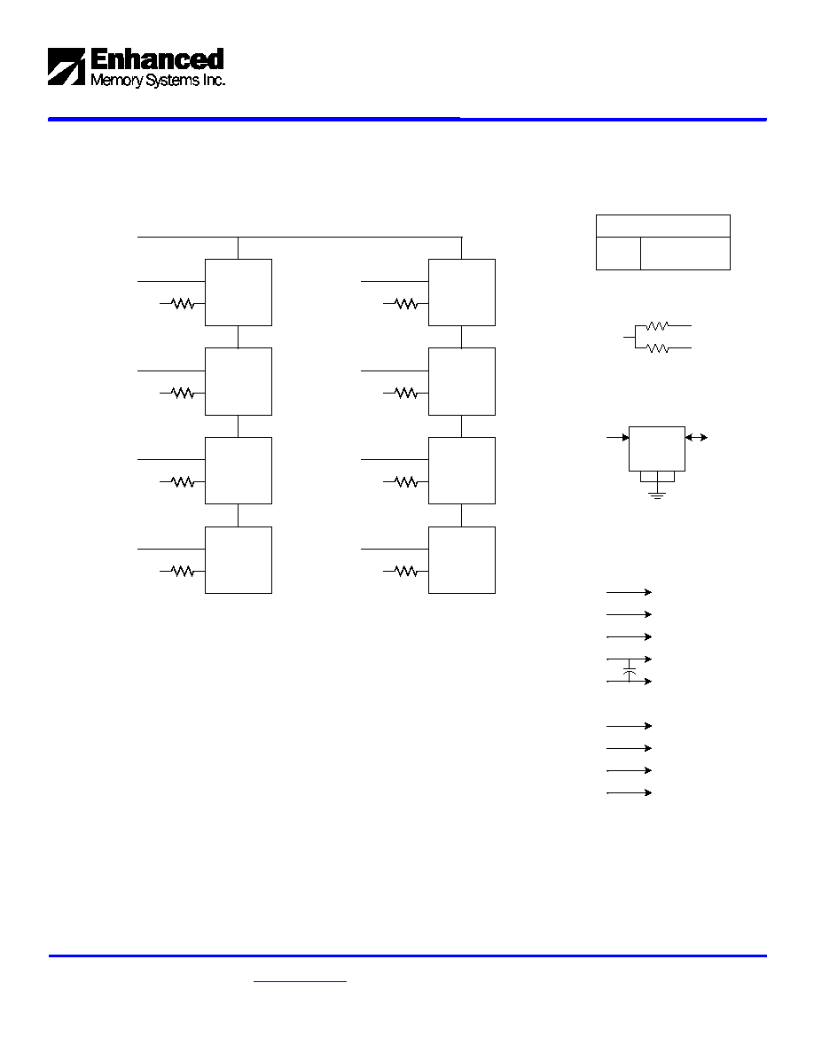
64MB DIMM Functional Block Diagram ≠ SM6408SDT
U0
U1
DQ(7:0)
DQMB0
S0#
DQ(15:8)
DQMB1
U2
U3
DQ(23:16)
DQMB2
DQ(31:24)
DQMB3
U4
U5
DQ(39:32)
DQMB4
DQ(47:40)
DQMB5
U6
U7
DQ(55:48)
DQMB6
DQ(63:56)
DQMB7
Clock Wiring
4 SDRAM
4 SDRAM
CK0
CK1
10
CK0, CK1
2 SDRAMs
Serial PD
SCL
A0 A1 A2
SDA
BA1 SDRAM U0-7
BA1
BA0 SDRAM U0-7
BA0
RAS# SDRAM U0-7
RAS#
A0-A11 SDRAM U0-7
A0-A11
Vdd SDRAM U0-7
Vdd
Vss SDRAM U0-7
Vss
CAS# SDRAM U0-7
CAS#
WE# SDRAM U0-7
WE#
CKE SDRAM U0-7
CKE0
Note:
All DQ resistor values are 10 ohms.
All CK resistor values are 10 ohms.
U0-U7 are 8Mx8 PC133 SDRAM devices.
10
2 SDRAMs

144-pin SDRAM SODIMMs
64MB, 128MB, 256MB, 512MB
Preliminary Data Sheet
Enhanced Memory Systems Inc., 1850 Ramtron Dr., Colo Spgs, CO 80921
2001 Enhanced Memory Systems. All rights reserved.
PHONE: (800) 545-DRAM; FAX: (719) 488-9095;
http://www.edram.com
The information contained herein is subject to change without notice.
Page 4 of 15
Revision 1.0
128MB DIMM Functional Block Diagram ≠ SM12808ASDT
U0
U1
DQ(7:0)
DQMB0
S0#
DQ(15:8)
DQMB1
U2
U3
DQ(23:16)
DQMB2
DQ(31:24)
DQMB3
U4
U5
DQ(39:32)
DQMB4
DQ(47:40)
DQMB5
U6
U7
DQ(55:48)
DQMB6
DQ(63:56)
DQMB7
Clock Wiring
4 SDRAM
4 SDRAM
CK0
CK1
10
CK0, CK1
2 SDRAMs
Serial PD
SCL
A0 A1 A2
SDA
BA1 SDRAM U0-7
BA1
BA0 SDRAM U0-7
BA0
RAS# SDRAM U0-7
RAS#
A0-A11 SDRAM U0-7
A0-A11
Vdd SDRAM U0-7
Vdd
Vss SDRAM U0-7
Vss
CAS# SDRAM U0-7
CAS#
WE# SDRAM U0-7
WE#
CKE SDRAM U0-7
CKE0
Note:
All DQ resistor values are 10 ohms.
All CK resistor values are 10 ohms.
U0-U7 are 16Mx8 PC133 SDRAM devices.
10
2 SDRAMs
144-pin SDRAM SODIMMs
Preliminary Data Sheet
64MB, 128MB, 256MB, 512MB
Enhanced Memory Systems Inc., 1850 Ramtron Dr., Colo Spgs, CO 80921
2001 Enhanced Memory Systems. All rights reserved.
PHONE: (800) 545-DRAM; FAX: (719) 488-9095;
http://www.edram.com
The information contained herein is subject to change without notice.
Revision 1.0
Page 5 of 15
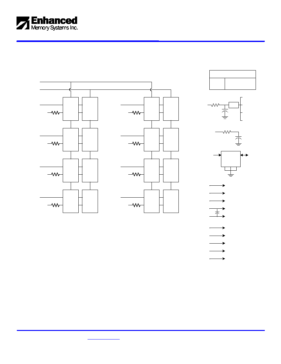
256MB DIMM Functional Block Diagram ≠ SM25608ASDT
DQ(7:0)
DQMB0
S0#
DQ(15:8)
DQMB1
DQ(23:16)
DQMB2
DQ(31:24)
DQMB3
DQ(39:32)
DQMB4
DQ(47:40)
DQMB5
DQ(55:48)
DQMB6
DQ(63:56)
DQMB7
U0L
U1L
U0U
U1U
U4L
U4U
U5L
U5U
U2L
U2U
U6L
U3L
U3U
U6U
U7L
U7U
S1#
BA1 SDRAM U0-7
BA1
BA0 SDRAM U0-7
BA0
RAS# SDRAM U0-7
RAS#
A0-A11 SDRAM U0-7
A0-A11
Vdd SDRAM U0-7
Vdd
Vss SDRAM U0-7
Vss
CAS# SDRAM U0-7
CAS#
WE# SDRAM U0-7
WE#
CKE0 SDRAM U0-3
CKE0
Note:
All DQ resistor values are 10 ohms.
All CK resistor values are 10 ohms.
U0-U7 are stacked 16Mx8 PC133 SDRAM devices.
Clock Wiring
PLL
Terminated
CK0
CK1
10
CK0
4 SDRAMs
Serial PD
SCL
A0 A1 A2
SDA
4 SDRAMs
10
CK1
4 SDRAMs
4 SDRAMs
CKE0 SDRAM U4-7
CKE1
12pf
12pf
PLL