 | –≠–ª–µ–∫—Ç—Ä–æ–Ω–Ω—ã–π –∫–æ–º–ø–æ–Ω–µ–Ω—Ç: DR2000-DK | –°–∫–∞—á–∞—Ç—å:  PDF PDF  ZIP ZIP |

RFM
DR2000
Development Board

2
DR2000 Virtual Wire
Æ
Æ
Development Kit Hardware Warranty
Limited Hardware Warranty. RF Monolithics, Inc. ("RFM") warrants solely to the purchaser that the
hardware components of the DR2000 Virtual WireÆ Development Kit (the "Kit") will be free from
defects in materials and workmanship under normal use for a period of 90 days from the date of
shipment by RFM. This limited warranty does not extend to any components which have been
subjected to misuse, neglect, accident, or improper installation or application. RFM's entire liability
and the purchaser's sole and exclusive remedy for the breach of this Limited Hardware Warranty
shall be, at RFM's option, when accompanied by a valid receipt, either (i) repair or replacement of
the defective components or (ii) upon return of the defective Kit, refund of the purchase price paid for
the Kit.
EXCEPT FOR THE LIMITED HARDWARE WARRANTY SET FORTH ABOVE, RFM AND
ITS LICENSORS PROVIDE THE HARDWARE ON AN "AS IS" BASIS, AND WITHOUT
WARRANTY OF ANY KIND EITHER EXPRESS, IMPLIED OR STATUTORY, INCLUDING BUT
NOT LIMITED TO THE IMPLIED WARRANTIES OF NONINFRINGEMENT, MERCHANTABILITY
OR FITNESS FOR A PARTICULAR PURPOSE. Some states do not allow the exclusion of implied
warranties, so the above exclusion may not apply to you. This warranty gives you specific legal rights
and you may also have other rights which vary from state to state.
Limitation of Liability. IN NO EVENT SHALL RFM OR ITS SUPPLIERS BE LIABLE FOR ANY
DAMAGES (WHETHER SPECIAL, INCIDENTAL, CONSEQUENTIAL OR OTHERWISE) IN
EXCESS OF THE PRICE ACTUALLY PAID BY YOU TO RFM FOR THE KIT, REGARDLESS OF
UNDER WHAT LEGAL THEORY, TORT, OR CONTRACT SUCH DAMAGES MAY BE ALLEGED
(INCLUDING, WITHOUT LIMITATION, ANY CLAIMS, DAMAGES, OR LIABILITIES FOR LOSS
OF BUSINESS PROFITS, BUSINESS INTERRUPTION, LOSS OF BUSINESS INFORMATION,
OR FOR INJURY TO PERSON OR PROPERTY) ARISING OUT OF THE USE OR INABILITY TO
USE THE KIT, EVEN IF RFM HAS BEEN ADVISED OF THE POSSIBILITY OF SUCH DAMAGES.
BECAUSE SOME STATES DO NOT ALLOW THE EXCLUSION OR LIMITATION OF LIABILITY
FOR CONSEQUENTIAL OR INCIDENTAL DAMAGES, THE ABOVE LIMITATION MAY NOT
APPLY TO YOU.
Special notice on restricted use of DR2000 Virtual Wire
Æ
Æ
Development Kits
DR2000 Virtual WireÆ Development Kits are intended for use solely by professional engineers for
the purpose of evaluating the feasibility of low-power wireless data communications applications.
The user's evaluation must be limited to use of an assembled Kit within a laboratory setting which
provides for adequate shielding of RF emission which might be caused by operation of the Kit
following assembly. In field testing, the assembled device must not be operated in a residential

3
area or any area where radio devices might be subject to harmful electrical interference. This Kit
has not been certified for use by the FCC in accord with Part 15, or to ETSI I-ETS 300 220 or
I-ETS 300 220-1 regulations, or other known standards of operation governing radio emissions.
Distribution and sale of the Kit is intended solely for use in future development of devices which
may be subject to FCC regulation, or other authorities governing radio emission. This Kit may not
be resold by users for any purpose. Accordingly, operation of the Kit in the development of future
devices is deemed within the discretion of the user and the user shall have all responsibility for
any compliance with any FCC regulation or other authority governing radio emission of such
development or use, including without limitation reducing electrical interference to legally
acceptable levels. All products developed by user must be approved by the FCC or other authority
governing radio emission prior to marketing or sale of such products and user bears all
responsibility for obtaining the FCC's prior approval, or approval as needed from any other
authority governing radio emission.
If user has obtained the Kit for any purpose not identified above, including all conditions of
assembly and use, user should return Kit to RF Monolithics, Inc. immediately.
The Kit is an experimental device, and RFM makes no representation with respect to the
adequacy of the Kit in developing low-power wireless data communications applications or
systems, nor for the adequacy of such design or result. RFM does not and cannot warrant that the
functioning of the Kit will be uninterrupted or error-free.
The Kit and products based on the technology in the Kit operate on shared radio channels. Radio
interference can occur in any place at any time, and thus the communications link may not be
absolutely reliable. Products using Virtual WireÆ technology must be designed so that a loss of
communications due to radio interference or otherwise will not endanger either people or property,
and will not cause the loss of valuable data. RFM assumes no liability for the performance of
products which are designed or created using the Kit.
RFM products are not suitable for use in
life-support applications, biological hazard applications, nuclear control applications, or
radioactive areas.
RFM and Virtual Wire are registered trademarks of RF Monolithics, Inc. MS-DOS, QuickBASIC,
and Windows are registered trademarks of Microsoft Corporation.

4
1.0 DR2000 Virtual WireÆ Development Kit Introduction
1.1 Purpose of the DR2000 Virtual Wire
Æ
Æ
Development Kit
The DR2000 Virtual Wire
Æ
Development Kit is a tool for evaluating the feasibility
of a low-power wireless data communications application. The kit also facilitates
the development of the actual system.
1.2 Intended Kit User
The DR2000 Virtual Wire
Æ
Development Kit is intended for use by a professional
engineer with a working knowledge of data communications. The kit itself is not
intended as an end product, or for use by individuals that do not have a
professional background in data communications. Please refer to the Special
Notices section in the front of this manual.
1.3 General Description
The DR2000 Virtual Wire
Æ
Development Kit allows the user to implement low-
power wireless communications based on half-duplex packet transmissions. The
kit contains the hardware and software needed to establish a wireless link
between two computers with RS232C serial ports. The kit includes two
communications nodes, with each node consisting of a data radio protocol
board, plus accessories. The DR2000-DK kit operates at 916.5 MHz.

5
1.4 Key Features
The DR2000 Virtual Wire
Æ
Development Kit includes a number of key features:
∑
"Out of the box" operation between two PC's
∑
3 Vdc low-current UHF data radio transceivers (916.5 MHz)
∑
Excellent receiver off-channel interference rejection
∑
Wide dynamic range receiver log detection and AGC for resistance to on-
channel interference
∑
Reference antennas
∑
3 Vdc low-current protocol boards based on an Analog Devices DSP
∑
On-board CMOS logic to RS232C level conversion
∑
Packet link-layer protocol with ISO 3309 error detection and automatic packet
retransmission; up to 255 message bytes per packet transmission (ASCII or
binary)
∑
DC-balanced data coding for robust RF transmission performance
∑
Simple packet protocol to application layer interface plus example application
software
∑
2 Bi-Color Leds for system performance evaluation
∑
Auto Transmission for range testing
∑
User
programmable RF and serial data speed
∑
User
programmable OOK & ASK Mode
∑
User
programmable node addresses
∑
User
programmable packet size
∑
User configuration retained in Flash memory
∑
NO PC required for Range testing
∑
Compatible with RFMs IC1000 Start bit & Clock Recovery IC

6
2
.0 Regulatory Certification
Regulatory Authority - Worldwide, man-made electromagnetic emissions are
controlled by international treaty and the ITU (International Telecommunications
Union) committee recommendations. These treaties require countries within a
geographical region to use comparable tables for channel allocations and
emission limits to assure that all users can operate with reasonable levels of
interference.
Recognizing a need to protect their limited frequency resources, many countries
have additional local laws, regulations, and government decrees for acceptable
emission levels from various electronic equipment, both military and commercial.
By requiring that each model of equipment be tested and an authorization permit
issued after payment of a tax (called a grant fee), the government attempts to
control the sale of poor quality equipment and also has record of the known
manufacturers.
Enforcement and expectation of the local law varies, of course. USA, Canada,
and most European countries have adopted ITU tables for their respective radio
regions. Australia, Hong Kong, and Japan also have extensive rules and
regulations for low-power transmitters and receivers, but with significant
differences in the tables for that radio region. Most other countries have less
formal regulations, often modeled on either USA or EU regulations.
In any country, it is important to contact the Ministry of Telecommunications or
Postal Services to determine any local limitations, allocations, or certifications
PRIOR to assembling or testing your first product. The mildest penalty is often
total loss of your import, export, and foreign exchange privileges.

7
These laws and requirements are applicable to the finished product, in the
configuration that it will be sold to the general public or the end user. OEM
components often can not be certified, since they require additional attachments
before they have any functional purpose.
Unless otherwise marked, RFM DR2000 Virtual Wire
Æ
Development Kit modules
have not been certified to any particular set of regulations. Each module has
suggested countries for use, depending on current allocations and technical
limits. Emissions from receivers can be an unexpected problem, and the RFM
modules have special features to help with this part of the emission testing.
Product Certification - General requirements for emissions and ingressions
(called susceptibility, if errors occur) are controlled by engineering standards of
performance, regulations, and the customer's expectations.
In USA and Canada, for example, you must formally measure the emissions, file
for a certification or authorization, and affix a permanent marking label to every
device, prior to offering your system for sale. Regulations allow you to build only
a small number (usually 5 pieces) for testing and in-company use, before
certification and marketing. Trade shows and product announcements can be a
problem for marketing, when the products are advertised without proper dis-
claimers. With Internet access, go to "www.fcc.org" for USA information or
"www.ic.gc.ca" for Canada. The Canada rules are RCC-210, Revision 2.
FCC CFR 47, Parts 2 and 15, contains the needed information for USA sales.
European Union (EU) requirements allow self-certification of some systems and
require formal measurement reports for other systems. In all cases, however, the
directives demand the "CE mark" be added to all compliant devices before any
device is freely shipped in commerce. In the EU, the EMC Directive also adds
various tests and expectations for levels of signal that will permit acceptable
operation.

8
The EU directives introduce the concepts of a "cognizant body", a "notification
body", and a "construction file". Cognizant bodies are simply technical experts
recognized by the EU committees to review technical regulations and
compliance. Any acceptable test lab will have a preferred cognizant body for
their certifications. Each regulatory body will have at least one engineer
designated as the notification body for that country, and he receives any
communication about certification or changes to a certified system. While this
may seem confusing, it does avoid the legal problems of engineering titles and
varied bureaucratic ministry names.
Construction files (CF) are a common format for presenting pictures, schematics,
and all other information on the parts and processes used to actually build a
certified system. The report of antenna range measurements will be included in
the CF. Your cognizant body will review the construction file before granting the
authorizations for CE mark and EU identification label on your system.
The first problem in the EU is usually Border Customs, who have been trained to
look for the CE logo marking for all products. You may need special forms or
permits to simply ship pre-production models to your test lab. The Internet web
site "www.etsi.co.fr" has information for ordering the full EU marketing
regulations.
Certification Testing -
The emissions are measured in a calibrated environment
defined by the regulations. USA and Canada use an "open field" range with 3
meters between the device under test (DUT) and the antenna. The range is
calibrated by measurement of known signal sources to generate range
attenuation (correction) curves in accordance with ANSI C63.4-1992.

9
EU measurement rules are based on a similar arrangement, but a "standard
dipole" antenna is substituted for the DUT to calibrate the range attenuation.
Since the EU measurements are comparison or substitution rules, they are often
easier to follow for informal pre-testing by the designer. ETSI-300-220 has
drawings to completely describe a typical test configuration.
The United States and Canadian requirements are contained in ANSI C63.4-
1992, including a step-by-step test calibration and measurement procedure.
Since these rules include range attenuation factors, one must make twice the
measurements of the EU test method. Other countries follow one of these two
techniques, with exception for a 10 meter range (separation) measurement or a
different range of test frequencies.
Each of the listed contacts will have resources to provide (for a fee) current
regulations and certification forms. They also can suggest sources for your
formal tests, either commercial labs or the government testing office. Unless you
want to invest in a qualified radiated signals test range, the commercial labs can
help with preliminary measurements and some expertise in correcting any
difficulties that are noted.
2
.1 Regulatory Certification Contacts
Contacts for further information and current test facilities listings:
ANSI
Institute of Electrical & Electronics Engineers,
345 East 47th Street, New York, NY 10017 USA
ETSI
European Telecommunications Standard Institute
F-06921 Sophia Antipolis Cedex FRANCE
FCC
Federal Communications Commission
Washington DC 20554 USA

10
Canada DOC
Industrie Canada
Attn: Certification, Engineering and Operations Section,
1241 Clyde Avenue, Ottawa K1A 0C8 CANADA
UNITED KINGDOM
LPRA (manufacturing association information)
Low Power Radio Association
The Old Vicarage, Haley Hill, Halifax HX3 6DR UK
or
Radiocommunications Agency (official)
Waterloo Bridge House, Waterloo Road
London SE1 8UA
JATE
Japan Approvals Institute (JATE)
Isomura Bldg, 1-1-3 Toranomon
Minato-ku Tokyo JAPAN

11
DR2000 PCB:
Led 1
Led 2
Led 3
RS232 I/O
ANT
RF ground
Power
Switch
Ground
2-4.5 VDC
or
3 VDC Battery
(2 AA)

12
Led Indicators:
Led1
Bi-color red and green Led.
Normal Rx / Tx operation
=
Green Flashing ~ 0.5 Hz
Range test ON
=
Red Flashing ~ 0.5Hz
Command Error
=
Green or Red Flashing ~0.2Hz
Led2
Yellow Led
RS232 I/O activity
=
Rxout Off
=
Led off
Rxout On
=
Led On for data out
Led3
Bi-color red and green Led.
Normal Rx / Tx Operation
=
Flash Green for receipt of GOOD Data
Flash RED for receipt of BAD Data
(Good data is FC1 & FC2 Match,
Bad data is FC1 and/or FC2 do not match)
ANT
Antenna Connection point
RF Ground
Antenna Ground point
Ground
Ground input for Board (-)
2-4-5 VDC
Power input to board (+)
2 to 4.5 VDC input from power supply or
1.5 to 3 VDC from 2 AA Batteries
RS232 I/O
Serial I/O and Hardware Flow Control I/O
RJ11 Connector

13
DR2000 Protocol Packet definition:
Start Symbol
Pre-amble 1 & 2
Pre-amble 3
B10000111111110
B10101110101010
B11010101010100
To Add
From Add
Pk Num Cmd
Length
Data
FCS1
FCS2
1 Byte
1 Byte
1 Byte
1 Byte
1 Byte
n Bytes
1 Byte
1 Byte
1-255
1-255
1-255
3-239
1-255
0-255
0-255
0-255
***** Pk Num MUST be at least 1 count different between packets (1,2,1,2 or 1,2,3,4,5)
Example of encoded data:
Data out(tx) Rotate(LSB to MSB)
Invert/drop st & sp
10000111111110
01111111100001
000000001111
Start Symbol
10101110101010
01010101110101
010101000101
Special Preamble 1
10101110101010
01010101110101
010101000101
Special Preamble 2
11010101010100
00101010101011
101010101010
AA hex Preamble 3
10111000011100
00111000011101
100011110001
31 hex To Address
11011000011100
00111000011011
100011110010
32 hex
From Address
st = start bit
sp = stop bit
Data shifted out lsb first
DC balanced Symbols Used in the DR2000:
0x0015, { NIBBLE = 0 010101 }
0x0031, { NIBBLE = 1 110001 }
0x0032, { NIBBLE = 2 110010 }
0x0023, { NIBBLE = 3 100011 }
0x0034, { NIBBLE = 4 110100 }
0x0025, { NIBBLE = 5 100101 }
0x0026, { NIBBLE = 6 100110 }
0x0016, { NIBBLE = 7 010110 }
0x001A, { NIBBLE = 8 011010 }
0x0029, { NIBBLE = 9 101001 }
0x002A, { NIBBLE = 10 101010 }
0x000B, { NIBBLE = 11 001011 }
0x002C, { NIBBLE = 12 101100 }
0x000D, { NIBBLE = 13 001101 }
0x000E, { NIBBLE = 14 001110 }
0x001C, { NIBBLE = 15 011100 }
A 31hex would be : 100011110001

14
Example of the Start Symbol, Preamble1,2 & 3 and the To & From Address, 31 & 32hex.
This is taken directly from the DR2000 while sending Range Test Data at the Txmod
input to the TR1000.

15
DR2000 Commands:
All commands
ARE case sensitive.
$$PCSPn
Change RS232 baud rate (default @ power up is 19.2kb)
n = 0 19200
n = 1 2400
n = 2 4800
n = 3
9600
n = 4
38400
n = 5
57600
n = 6
115200
Response
PC baud rate = nnnnn
$$RDSPn
Change RF baud rate (this value is stored in flash memory)
n = 0 57600
n = 1 2400
n = 2 4800
n = 3
9600
n = 4
19200
n = 5
38400
n = 6
115200
Response
RF baud rate = nnnnn
$$RFMDn
Change RF Tx Mode (this value is stored in flash memory)
n = 0
OOK
n = 1
ASK
Response
RF mode = nnn

16
DR2000 Commands (continued):
$$TOADhh
Change `To' address (in hex)
Valid digits: 0-f (00 ≠ ff)
To Address of `00' is used for Broadcast
(this value is stored in flash memory)
Response
To Address = nn
$$FRADhh
Change `FROM' address (in hex)
Valid digits: 0-9, a-f (00 ≠ ff)
(this value is stored in flash memory)
Response
From Address = nn
$$SIZEhh
Change Packet size (in hex)
Valid digits: 0-9, a-f (01 ≠ ff)
Recommended packet size is 64 (40h)
(this value is stored in flash memory)
Response
Packet Size = nn
$$RCSTn
Turn on data output via RS232. This is the output control
n = 0
Rx output off
n = 1
Rx output on
Response
Rxout = on/off
$$RANGn
`Range Test' (auto transmit)
n = 0
Range test off
n = 1
Range test on
Range test data sent =
" Range Test Data "
To display the data on remote, RCST must be on.
Response
Range on/off

17
DR2000 Commands (continued):
$$s
Display current DR2000 configuration
Example:
RF mode OOK
To Address = 31
From Address = 32
Packet Size = 40
Range on
Rxout on
To address is 31 hex (49)
From Address is 32 hex (50)
Packet size is 40 hex (64)
Range test is ON
RS232 output is on
$$^s
Control s = Xon/Xoff flow control disabled
Response
XON-XOFF Disabled
$$^q
Control q = Xon/Xoff flow control enabled
Response
XON-XOFF enabled
$$SCTSn
Enable / Disable Hardware flow control
n = 0 Disable Hardware flow control
n = 1
Enable Hardware flow control
Response
SCTS OFF/ON

18
DR2000 Commands (continued):
$$?
Display valid commands
Response:
$$s
= $$s Received, display status
$$^s
= Xon-Xoff Disabled
$$^q
= Xon-Xoff Enabled
$$PCSP
= PC Baud Rate
$$RDSP
= RF Baud Rate
$$RFMD
= RF mode
$$TOAD
= Set To Address
$$FRAD
= Set From Address
$$SIZE
= Set Packet Address
$$STMD
= Set Mode
$$SCTS
= Set CTS
$$REST
= Reset
$$??
= HELP

19
DR2000 Remote Commands:
These commands will change to configuration of the remote DR2000 when
their Address is equal to "TO address".
$&PCSPn
Change remote RS232 baud rate (default @ power up is 19.2kb)
n = 0 19200
n = 1 2400
n = 2 4800
n = 3
9600
n = 4
38400
n = 5
57600
n = 6
115200
Response
Message sent to remote
$&RDSPn
Change remote RF baud rate (this value is stored in flash memory)
Care must be taken to change remote RF baud rate first
n = 0 57600
n = 1 2400
n = 2 4800
n = 3
9600
n = 4
19200
n = 5
38400
n = 6
115200
Response
Message sent to remote
$&RFMDn
Change remote RF Tx Mode
n = 0
OOK
n = 1
ASK
(this value is stored in flash memory)
Response
Message sent to remote
$&TOADhh
Change remote `To' address (in hex)
Valid digits: 0-f (00 ≠ ff)
To Address of `00' is used for Broadcast
(this value is stored in flash memory)
Response
Message sent to remote

20
DR2000 Remote Commands (continued):
$&FRADhh
Change remote `FROM' address (in hex)
Valid digits: 0-9, a-f (00 ≠ ff)
(this value is stored in flash memory)
Response
Message sent to remote
$&SIZEhh
Change remote Packet size (in hex)
Valid digits: 0-9, a-f (01 ≠ ff)
Recommended packet size is 64 (40h)
(this value is stored in flash memory)
Response
Message sent to remote
$&RCST
Turn on remote data output via RS232. This is the output control
n = 0
Rx output off
n = 1
Rx output on
Response
Message sent to remote
21
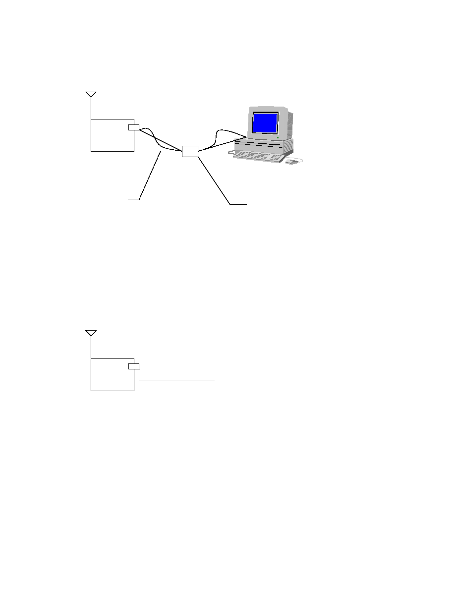
DR2000 Setup:
DR2000
DB9 to
RJ11
Supplied
6 Conductor
RJ11 Cable
Supplied
DB9 Plugs Directly into
PC Serial Port
DR2000
No PC
Connection
Needed

22

23

24

25

26
Bill Of Materials for DR2000
Reference VALUE Qty
PN
Size
-----------------------------------------------------------------------
U10 ST16C1550 1
500-0839-001 PLCC28SQ
Q2,4 2N2907 2
500-0653-001 SOT23
Q3 2N2222 1
500-0183-001 SOT23
D6 MBR0520 1
500-0841-001 1210
U8 74LVX273 1
500-0800-001 SO20
U13 74LVX04 1
500-0838-001 SO14
U9 74LVX32 1
500-0807-001 SO14
U7 AD7822 1
500-0789-001 RU-20
U1 ADSP2186L 1
500-0790-001 TQFP100
U2 AM29LV001 1
500-0808-001 PLCC32
U11,12 CMD67-22RUGC/8 2 500-0798-001 BI-LED
C17,19 .015uf 2
500-0621-153 0603
C21,22 27PF 2
500-0621-270 0603
C30,36,3,31,34,33,10,13 1000PF 8
500-0621-102 0603
C32,37 22uf 2
500-0801-223 1210
C38 4.7uf 0
500-0804-047 1206
C39 0.33uf 0
500-0802-003 1206
C1,2,25,26 33PF 4
500-0621-330 0603
C7,18,20 0.1uf 3
500-0621-104 0603
C6,8,9,11,12,14,15,16,23,24 0.1uf 10
500-0621-104 0603
C27,28,35 1uf 3
500-0243-105 1206
J1 RJ11 1
500-0812-001 6 POS
L1,2 10uH 2
500-0840-001 1206
L3 10nH 1
500-0739-100 0603
L4 18nH 1
500-0739-180 0603
U6 LT1308 1
500-0795-001 SO8
U4 MAX811 1
500-0809-001 SOT143
R1,3,4 330 3
500-0620-331 0603
R2 30k 1
500-0620-303 0603
R5,6 600 0
500-0620-601 0603
R19,23,25,27,14,34 10k 6
500-0620-103 0603
R32 1k 1
500-0620-102 0603
R9 1.3k 0
500-0620-132 0603
R10 2.4M 0
500-0620-245 0603
R11 18k 0
500-0620-183 0603
R18 1M 1
500-0620-105 0603
R20,21,22,17 2.7K 4
500-0620-272 0603
R35 1.02M 1
500-0620-105 0603
R36 608k 1
500-0620-604 0603
R37,31,33 100k 3
500-0620-104 0603
R15 30k 1
500-0620-303 0603
R16,26,38 51k 3
500-0620-513 0603
R24 100 1
500-0620-101 0603
R29,30 270k 2
500-0620-274 0603
R41 F.BEED 1
500-0764-001 0603
R42 820 1
500-0620-821 0603
R43 3.7k 1
500-0620-372 0603
R44,45 470 2
500-0620-471 0603
S1 SW1 1
500-0724-001

27
Bill Of Materials for DR2000
Reference VALUE Qty
PN
SIZE
A1 TR1000
1
TR1000 916.5MHZ
Y1 16.87MHZ
1
500-0792-001 HC49U
Y2 1.8432MHZ
1
500-0837-001 HC49U
D2 CMD67-21VYC/TR8 1
500-0799-001 YEL LED
B1
BH2AA-PC
1
500-0836-001 2 PIN
SK1
32PLCC SOCKET 1
500-0797-001 PLCC32

28
RS232 Connector wiring:
DB9 Female _____ RG11-6 (Straight) Signal
Pin1 & Pin 6
Blue
DCD
Pin2
Black
RX
Pin3
Red
TX
Pin4
N/C
Pin5
White
Ground
Pin6
Yellow
DSR
Pin7
N/C
Pin8
Green
CTS
Pin9
N/C
Green
White
Red
Black
Blue
Yellow

29
DR2000 Packet Protocol Example:
Setup for data transmission from
LOCAL to REMOTE:
1.
Enter the following commands on the
LOCAL DR2000:
∑
$$TOAD31
;set "TO" address to hex 31
∑
$$FRAD32
;set "FROM" address to hex 32
∑
$$SIZE20
;set packet "SIZE" to hex 20 (32dec.)
∑
$$RFMD0
;set RF mode to OOK
∑
$$RDSP4
;set RF TX Speed to 19.2kbaud
∑
$$RCST1
;enable data out to PC
1.
Enter the following commands on the
REMOTE DR2000:
∑
$$TOAD32
;set "TO" address to hex 32
∑
$$FRAD31
;set "FROM" address to hex 31
∑
$$SIZE20
;set packet "SIZE" to hex 20 (32dec.)
∑
$$RFMD0
;set RF mode to OOK
∑
$$RDSP4
;set RF TX Speed to 19.2kbaud
∑
$$RCST1
;enable data out to PC
To Add
From Add
Pk Num Cmd
Length
Data
1 Byte
1 Byte
1 Byte
1 Byte
1 Byte
n Bytes
1-255
1-255
1-255
3-239
1-255
0-255
***** Pk Num MUST be at least 1 count different between packets (1,2,1,2 or 1,2,3,4,5)
1.
Send the following from the
LOCAL DR2000: (
in hex
)
313201051d4142434445464748494a4b4c4d4e4f505152535455565758595a31
This will send the following data from the
LOCAL DR2000 Address 32 TO the
REMOTE DR2000 address 31. The REMOTE display will print
"ABCDEFGHIJKLMNOPQRSTUVWXYZ1".
1.
Send the following from the
REMOTE DR2000: (
in hex
)
323101051d4142434445464748494a4b4c4d4e4f505152535455565758595a31
This will send the following data from the
REMOTE DR2000 Address 31 TO the
LOCAL DR2000 address 32. The LOCAL display will print
"ABCDEFGHIJKLMNOPQRSTUVWXYZ1".
Note1:
∑
Length is calculated as data byte count + 2 (FCS1 & FCS2)
∑
In the above example data byte count is 27 + 2 = 29 (1b hex)

30
Note2:
Telix, a terminal program capable of running script programs is available at:
for either Windows or DOS. Telix is available for purchase or shareware.
DR2000 Range Test Example:
Setup for Range test from
LOCAL to REMOTE:
1.
Enter the following commands on the
LOCAL DR2000:
∑
$$TOAD31
;set "TO" address to hex 31
∑
$$FRAD32
;set "FROM" address to hex 32
∑
$$RFMD0
;set RF mode to OOK
∑
$$RFSP4
;set RF TX Speed to 19.2kbaud
∑
$$RCST1
;enable data out to PC
2.
Enter the following commands on the
REMOTE DR2000:
∑
$$TOAD32
;set "TO" address to hex 32
∑
$$FRAD31
;set "FROM" address to hex 31
∑
$$RFMD0
;set RF mode to OOK
∑
$$RFSP4
;set RF TX Speed to 19.2kbaud
∑
$$RCST1
;enable data out to PC
3.
Enter the following commands on the
LOCAL DR2000 to start the test:
∑
$$RANG1
4.
The following data is now being sent to the REMOTE DR2000:
∑
" Range Test Data "
5.
Enter the following to stop the range test:
∑
$$RANG0

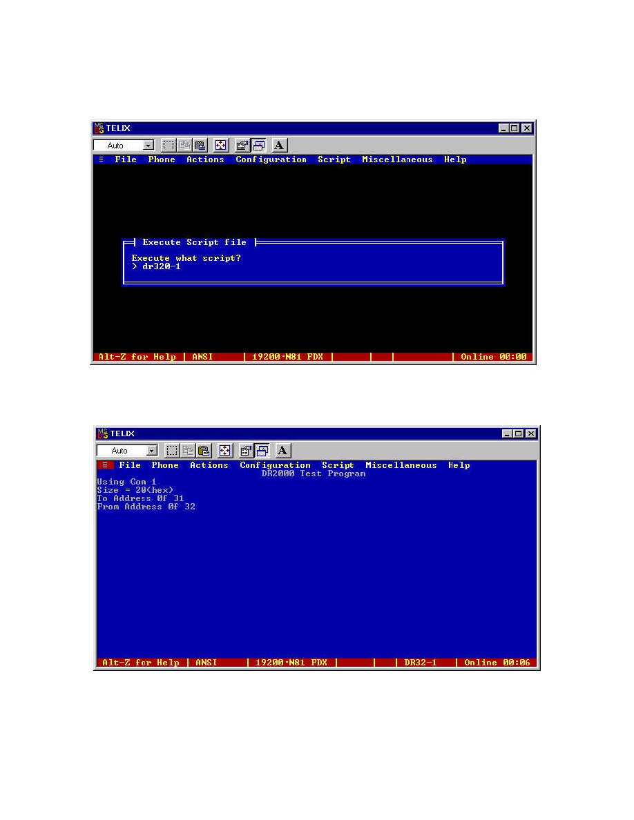
DR2000 Instructions for sending 32 byte packets using Telix for Dos.
1.
Connect DR2000 to Com 1
2.
Start Telix
3.
Turn the DR2000 power on
4.
Display should look like this:
If this is correct go to step # 5
Else
To change to address enter in Caps $$TOAD31
To change from address enter in Caps $$FRAD32
To change Size enter in Caps $$SIZE20
Label this DR2000 as master.
5.
Unplug the DR2000 and plug DR2000 # 2 into Com 1
6.
Turn DR2000 power on

7.
The display should look like:
If this is correct go to step # 8
Else
To change to address enter in Caps $$TOAD32
To change from address enter in Caps $$FRAD31
To change Size enter in Caps $$SIZE20
Label this DR2000 as slave.
Turn power off and back on and ensure display is the same as above
8.
Unplug DR2000 labeled "Salve" leaving it turned on.
9.
Plug DR2000 labeled "Master" and turn the power on
10.
Ensure display look like this:
11.
If the display is NOT correct go to to the # 1 and start again
12.
Press "Alt g " on the PC and enter DR32-1 for Com port 1 or DR32-2 for Com port 2
13.
Display should look like:
14.
Press Enter on the PC
15.
The Telix screen should look like:

16.
The Green LED should now be flashing RED on the DR2000 that is Master
17.
The "Slave DR2000 should have 2 Green LED's flashing along with the center yellow LED
flashing.
18.
To exit the script press Esc on the PC until you get the following message:
Press "Y" for yes
19.
The script is now stopped.
Note:
The DR2000 looks at the From address to ensure you are talking to it. If you have the master and
slave swapped, the DR2000 will not transmit the packet. So ensure the master address is as stated
above.