RF Monolithics, Inc.
Phone: (972) 233-2903
Fax: (972) 387-8148
E-mail: info@rfm.com
Page 1 of 2
RFM Europe
Phone: 44 1963 251383
Fax: 44 1963 251510
http://www.rfm.com
©1999 by RF Monolithics, Inc. The stylized RFM logo are registered trademarks of RF Monolithics, Inc.
RF1183-082701
Electrical Characteristics
Characteristic
Sym
Notes
Minimum
Typical
Maximum
Units
Center Frequency at 25∞C Absolute Frequency
f
C
1, 2
309.020
310.080
MHz
Tolerance from 303.825
f
C
±80
kHz
Insertion Loss
IL
1
1.4
5.0
dB
3 dB Passband
BW
3
1, 2
500
600
800
kHz
Rejection
at f
c
- 21.4 MHz (Image)
1
45
50
dB
at f
c
- 10.7 MHz (LO)
15
40
Ultimate
80
Temperature
Operating Case Temp.
T
C
3, 4
-35
+85
∞C
Turnover Temperature
T
O
24
39
54
Turnover Frequency
f
O
f
C
MHz
Freq. Temp. Coefficient
FTC
0.032
ppm/∞C
2
Frequency Aging
Absolute Value during the First Year
|fA|
5
10
ppm/yr
External Impedance
Series Inductance
L
1
85
nH
Shunt Capacitance
C
5
18
pF
Lid Symbolization (in addition to Lot and/or Date Codes)
RFM RF1183
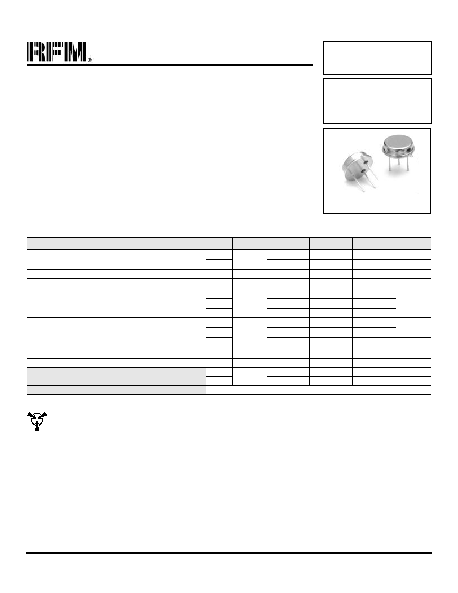
TO39-3 Case
∑
Ideal Front-End Filter for 310.0 MHz Wireless Receivers
∑
Low-Loss, Coupled-Resonator Quartz Design
∑
Simple External Impedance Matching
∑
Rugged TO39 Hermetic Package
The RF1183 is a low-loss, compact, and economical surface-acoustic-wave (SAW) filter designed to provide front-end
selectivity in 310.0 MHz receivers. Receiver designs using this filter include superhet with 10.7 MHz or 500 kHz IF, direct
conversion, and superregen. Typical applications of these receivers are wireless remote-control and security devices
operating in the USA under FCC Part 15, in Canada under DoC RSS-210, and in Italy.
This coupled-resonator filter (CRF) uses selective null placement to provide suppression, typically greater than 40 dB, of
the LO and Image spurious responses of superhet receivers with 10.7 MHz IF. RFM's advanced SAW design and
fabrication technology is utilized to achieve high performance and very low loss with simple external impedance matching
(not included). Quartz construction provides excellent frequency stability over a wide temperature range.
310.0 MHz
SAW Filter
RF1183
CAUTION: Electrostatic Sensitive Device. Observe precautions for handling.
Notes:
1. Unless noted otherwise, all measurements are made with the filter installed in the specified test fixture which is connected to a 50
test system with
VSWR
1.2:1. The test fixture L and C are adjusted for minimum insertion loss at the filter center frequency, f
c
. Note that insertion loss, bandwidth,
and passband shape are dependent on the impedance matching component values and quality.
2. The frequency f
c
is defined as the midpoint between the 3dB frequencies.
3. Unless noted otherwise, specifications apply over the entire specified operating temperature range.
4. The turnover temperature, T
O
, is the temperature of maximum (or turnover) frequency, f
o
. The nominal frequency at any case temperature, T
c
, may
be calculated from: f = f
o
[1 - FTC (T
o
- T
c
)
2
].
5. Frequency aging is the change in fc with time and is specified at +65∞C or less. Aging may exceed the specification for prolonged temperatures
above +65∞C. Typically, aging is greatest the first year after manufacture, decreasing significantly in subsequent years.
6. The design, manufacturing process, and specifications of this device are subject to change without notice.
7. One or more of the following U.S. Patents apply: 4,54,488, 4,616,197, and others pending.
8. All equipment designs utilizing this product must be approved by the appropriate government agency prior to manufacture or sale.
