
RF Monolithics, Inc.
Phone: (972) 233-2903
Fax: (972) 387-9148
E-mail: info@rfm.com
Page 1 of 2
RFM Europe
Phone: 44 1963 251383
Fax: 44 1963 251510
http://www.rfm.com
©1999 by RF Monolithics, Inc. The stylized RFM logo are registered trademarks of RF Monolithics, Inc.
RO2021-102199
Electrical Characteristics
Characteristic
Sym
Notes
Minimum
Typical
Maximum
Units
Frequency (+25 ∞C)
Nominal Frequency
f
C
2, 3, 4, 5
417.975
418.125
MHz
Tolerance from 418.050 MHz
f
C
±75
kHz
Insertion Loss
IL
2, 5, 6
2.5
7.0
dB
Quality Factor
Unloaded Q
Q
U
5, 6, 7
11,300
50
Loaded Q
Q
L
2,800
Temperature Stability
Turnover Temperature
T
O
6, 7, 8
41
56
71
∞C
Turnover Frequency
f
O
f
C
+15
kHz
Frequency Temperature Coefficient
FTC
0.037
ppm/∞C
2
Frequency Aging
Absolute Value during the First Year
|fA|
1, 6
10
ppm/yr
DC Insulation Resistance between Any Two Pins
5
1.0
M
RF Equivalent RLC Model
Motional Resistance
R
M
5, 6, 7, 9
33
124
Motional Inductance
L
M
141.965
µH
Motional Capacitance
C
M
1.02095
fF
Pin 1 to Pin 2 Static Capacitance
C
O
5, 6, 9
2.1
2.4
2.7
pF
Transducer Static Capacitance
C
P
5, 6, 7, 9
2.1
pF
Test Fixture Shunt Inductance
L
TEST
2, 7
66
nH
Lid Symbolization (in addition to Lot and/or Date Codes)
RFM 2021
TO39-3 Case
∑
Designed for 418.05 MHz Transmitter Applications
∑
Low Series Resistance
∑
Quartz Stability
∑
Rugged, Hermetic, Low-Profile TO39 Case
∑
Complies with Directive 2002/95/EC (RoHS)
The RO2021 is a true one-port, surface-acoustic-wave (SAW) resonator in a low-profile TO39 case. It pro-
vides reliable, fundamental-mode quartz frequency stabilization, of fixed frequency transmitters operating at
418.050 MHz. The RO2021 is designed specifically for remote control and wireless security AM transmitters
operating in the United Kingdom under DTI MPT 1340 and in the USA under FCC Part 15.
Absolute Maximum Ratings
Rating
Value
Units
CW RF Power Dissipation (See: Typical Test Circuit)
+5
dBm
DC Voltage Between Any Two Pins (Observe ESD Precautions)
±30
VDC
Case Temperature
-40 to +85
∞C
418.05 MHz
SAW
Resonator
RO2021
CAUTION: Electrostatic Sensitive Device. Observe precautions for handling.
Notes:
1.
Frequency aging is the change in f
C
with time and is specified at +65∞C or less.
Aging may exceed the specification for prolonged temperatures above +65∞C.
Typically, aging is greatest the first year after manufacture, decreasing signifi-
cantly in subsequent years.
2.
The center frequency, f
C
, is measured at the minimum insertion loss point, IL
MIN
,
with the resonator in the 50
test system (VSWR
1.2:1). The shunt induc-
tance, L
TEST
, is tuned for parallel resonance with C
O
at f
C
. Typically, f
OSCILLA-
TOR
or f
TRANSMITTER
is less than the resonator f
C
.
3.
One or more of the following United States patents apply: 4,454,488 and
4,616,197 and others pending.
4.
Typically, equipment designs utilizing this device require emissions testing and
government approval, which is the responsibility of the equipment manufacturer.
5.
Unless noted otherwise, case temperature T
C
= +25∞C±2∞C.
6.
The design, manufacturing process, and specifications of this device are subject
to change without notice.
7.
Derived mathematically from one or more of the following directly measured
parameters: f
C
, IL, 3 dB bandwidth, f
C
versus T
C
, and C
O
.
8.
Turnover temperature, T
O
, is the temperature of maximum (or turnover) fre-
quency, f
O
. The nominal frequency at any case temperature, T
C
, may be calcu-
lated from: f = f
O
[1 - FTC (T
O
-T
C
)
2
]. Typically,
oscillator T
O
is 20∞C less than
the specified
resonator T
O
.
9.
This equivalent RLC model approximates resonator performance near the reso-
nant frequency and is provided for reference only. The capacitance C
O
is the
static (nonmotional) capacitance between pin1 and pin 2 measured at low fre-
quency (10 MHz) with a capacitance meter. The measurement includes case
parasitic capacitance with a floating case. For usual grounded case applica-
tions (with ground connected to either pin 1 or pin 2 and to the case), add
approximately 0.25 pF to C
O
.
Pb
418.05 MHz SAW Resonator
RF Monolithics, Inc.
Phone: (972) 233-2903
Fax: (972) 387-9148
E-mail: info@rfm.com
Page 2 of 2
RFM Europe
Phone: 44 1963 251383
Fax: 44 1963 251510
http://www.rfm.com
©1999 by RF Monolithics, Inc. The stylized RFM logo are registered trademarks of RF Monolithics, Inc.
RO2021-102199
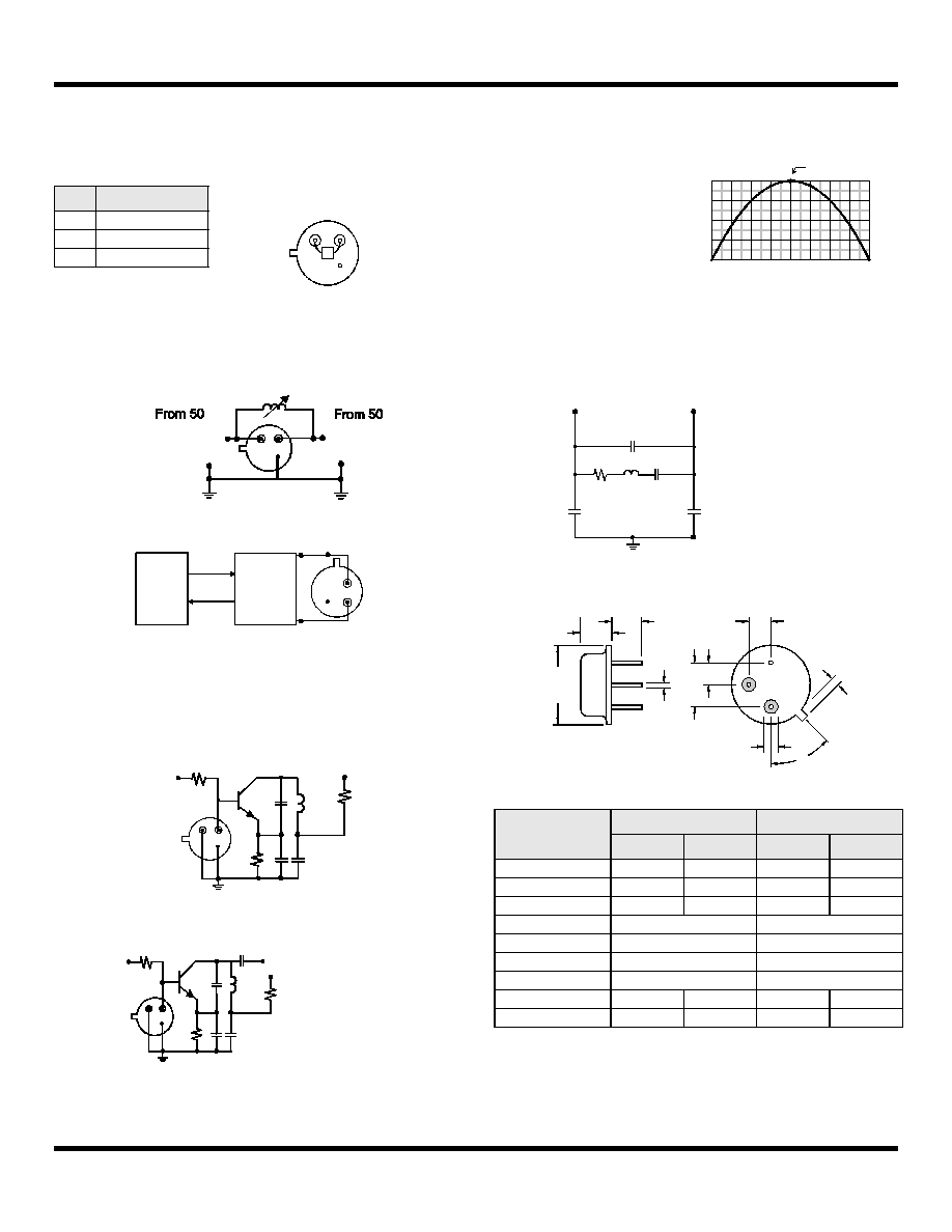
Electrical Connections
This one-port, two-terminal SAW resonator is bidirectional. The terminals
are interchangeable with the exception of circuit board layout.
Typical Test Circuit
The test circuit inductor, L
TEST
, is tuned to resonate with the static capaci-
tance, C
O
at F
C
.
Typical Application Circuits
Temperature Characteristics
Equivalent LC Model
The following equivalent LC model is valid near resonance:
Case Design
Pin
Connection
1
Terminal 1
2
Terminal 2
3
Case Ground
Network
Analyzer
Network
Analyzer
Electrical Test:
1
2
3
50
Source at
FC
Low-Loss
Matching
Network
50
to
Power Test:
P
P
INCIDENT
INCIDENT
CW RF Power Dissipation =
-
REFLECTED
REFLECTED
P
P
3
2
1
MPS-H10
+9VDC
47
RF Bypass
L1
C1
C2
200k
Modulation
Input
ROXXXX
Bottom View
470
Typical Low-Power Transmitter Application:
1
2
3
(Antenna)
+VDC
RF Bypass
L1
C2
ROXXXX
Bottom View
Typical Local Oscillator Application:
1
2
3
Output
+VDC
C1
Dimensions
Millimeters
Inches
Min
Max
Min
Max
A
9.40
0.370
B
3.18
0.125
C
2.50
3.50
0.098
0.138
D
0.46 Nominal
0.018 Nominal
E
5.08 Nominal
0.200 Nominal
F
2.54 Nominal
0.100 Nominal
G
2.54 Nominal
0.100 Nominal
H
1.02
0.040
J
1.40
0.055
The curve shown on the right
accounts for resonator contri-
bution only and does not in-
clude oscillator temperature
characteristics.
-80 -60 -40 -20
0 +20 +40 +60
0
-50
-100
-150
+80
-200
0
-50
-100
-150
-200
f
C
= f
O
, T
C
= T
O
T =
T
C
- T
O
( ∞C )
(f-
f o
o
) /
f
(ppm
)
0.5 pF*
0.25 pF*
Cp
Co=
+
*Case Parasitics
R
L
C
0.5 pF*
Cp
1
2
3
M
M
M
B
45∞
J
(2 places)
D
(3 places)
H
G
E
F
C
A
Bottom View
Pin 1
Pin 2
Pin 3