 | –≠–ª–µ–∫—Ç—Ä–æ–Ω–Ω—ã–π –∫–æ–º–ø–æ–Ω–µ–Ω—Ç: NDA-410-D | –°–∫–∞—á–∞—Ç—å:  PDF PDF  ZIP ZIP |

Se
e Up
gr
aded Pr
od
uc
t N
BB-300-
D
NO
T
FOR
N
EW
DE
SI
GNS
4-113
Product Description
Ordering Information
Typical Applications
Features
Functional Block Diagram
RF Micro Devices, Inc.
7628 Thorndike Road
Greensboro, NC 27409, USA
Tel (336) 664 1233
Fax (336) 664 0454
http://www.rfmd.com
Optimum Technology MatchingÆ Applied
Si BJT
GaAs MESFET
GaAs HBT
Si Bi-CMOS
SiGe HBT
Si CMOS
InGaP/HBT
GaN HEMT
SiGe Bi-CMOS
NDA-410-D
InGaP/GaAs HBT MMIC DISTRIBUTED
AMPLIFIER DC TO 11GHz
∑ Narrow and Broadband Commercial and
Military Radio Designs
∑ Linear and Saturated Amplifiers
∑ Gain Stage or Driver Amplifiers for
MWRadio/Optical Designs
The NDA-410-D InGaP/GaAs HBT MMIC distributed
amplifier is a low-cost, high-performance solution for high
frequency RF, microwave, or optical amplification needs.
This 50
matched distributed amplifier is based on a reli-
able HBT proprietary MMIC design, providing unsur-
passed performance for small-signal applications.
Designed with an external bias resistor, the NDA-410-D
provides flexibility and stability. In addition, the
NDA-410-D chip was designed with an additional ground
via to enable low junction temperature operation.
NDA-series of distributed amplifiers provide design flexi-
bility by incorporating AGC functionality into their designs.
∑ Reliable, Low-Cost HBT Design
∑ 12.0dB Gain, +15.5dBm P1dB@2GHz
∑ High P1dB ofInGaP +14.8dBm@6.0GHz
and +13.5dBm@11.0GHz
∑ Fixed Gain or AGC Operation
∑ 50
I/O Matched for High Freq. Use
NDA-410-D
InGaP/GaAs HBT MMIC Distributed Amplifier DC to
11GHz - Die Only (100 pieces minimum order)
0
Rev A5 030912
GND
OUTPUT
GND
VIA
GND
VIA
INPUT
VCC1
GND
GND
0.022 ± 0.001
[0.57 ± 0.03]
0.027 ± 0.001
[0.68 ± 0.03]
0.004 ± 0.001
[0.10 ± 0.03]
Package Style: Die
NOT FOR NEW DESIGNS
See Upgraded Product NBB-300-D
4-114
NDA-410-D
Rev A5 030912
NO
T
FOR
N
EW
DE
SI
GNS
Se
e Up
gr
aded Pr
od
uc
t N
BB-300-
D
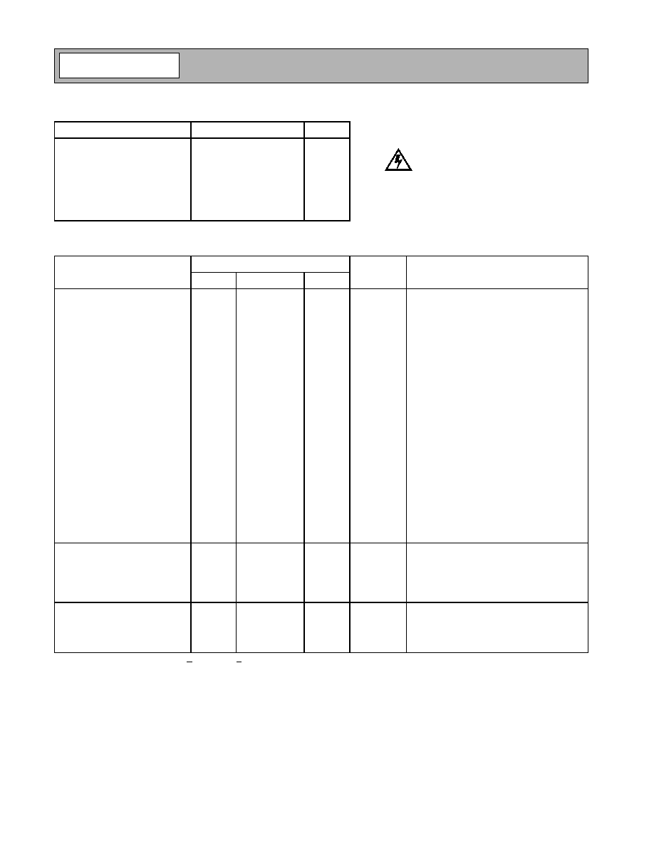
Absolute Maximum Ratings
Parameter
Rating
Unit
RF Input Power
+15
dBm
Power Dissipation
300
mW
Device Current, I
CC1
42
mA
Device Current, I
CC2
42
mA
Junction Temperature, Tj
200
∞C
Operating Temperature
-45 to +85
∞C
Storage Temperature
-65 to +150
∞C
Exceeding any one or a combination of these limits may cause permanent damage.
Parameter
Specification
Unit
Condition
Min.
Typ.
Max.
Overall
V
CC1
=+10V, V
CC2
=+10V, V
C1
=+4.7V,
V
C2
=+2.98V, I
CC1
=29mA, I
CC2
=36mA,
Z
0
=50
, T
A
=+25∞C
Small Signal Power Gain, S21
12.0
13.0
dB
f=0.1GHz to 4.0GHz
13.0
dB
f=4.0GHz to 6.0GHz
13.0
dB
f=6.0GHz to 8.0GHz
9.0
10.0
dB
f=8.0GHz to 11.0GHz
Input and Output VSWR
1.35:1
f=0.1GHz to 4.0GHz
2.3:1
f=4.0GHz to 8.0GHz
3.50:1
f=8.0GHz to 11.0GHz
Bandwidth, BW
11.0
GHz
BW3 (3dB)
Output Power @
1dB Compression
15.5
dBm
f=2.0GHz
14.8
dBm
f=6.0GHz
13.5
dBm
f=11.0GHz
Noise Figure, NF
5.0
dB
f=2.0GHz
Third Order Intercept, IP3
+25.5
dBm
f=2.0GHz
Reverse Isolation, S12
-16.0
dB
f=0.1GHz to 11.0GHz
Output Device Voltage, V
C2
2.70
2.98
3.20
V
AGC Control Voltage, V
C1
4.7
V
Gain Temperature Coefficient,
G
T
/
T
-0.0015
dB/∞C
MTTF versus
Junction Temperature
Case Temperature
85
∞C
Junction Temperature
144
∞C
MTTF
>1,000,000
hours
Thermal Resistance
JC
242
∞C/W
Suggested Voltage Supply: V
CC1
>4.7V, V
CC2
>5.0V
J
T
T
CASE
≠
V
D
I
CC
---------------------------
JC
∞C Watt
/
(
)
=
Caution! ESD sensitive device.
RF Micro Devices believes the furnished information is correct and accurate
at the time of this printing. However, RF Micro Devices reserves the right to
make changes to its products without notice. RF Micro Devices does not
assume responsibility for the use of the described product(s).
4-115
NDA-410-D
Rev A5 030912
NO
T
FOR
N
EW
DE
SI
GNS
Se
e Up
gr
aded Pr
od
uc
t N
BB-300-
D
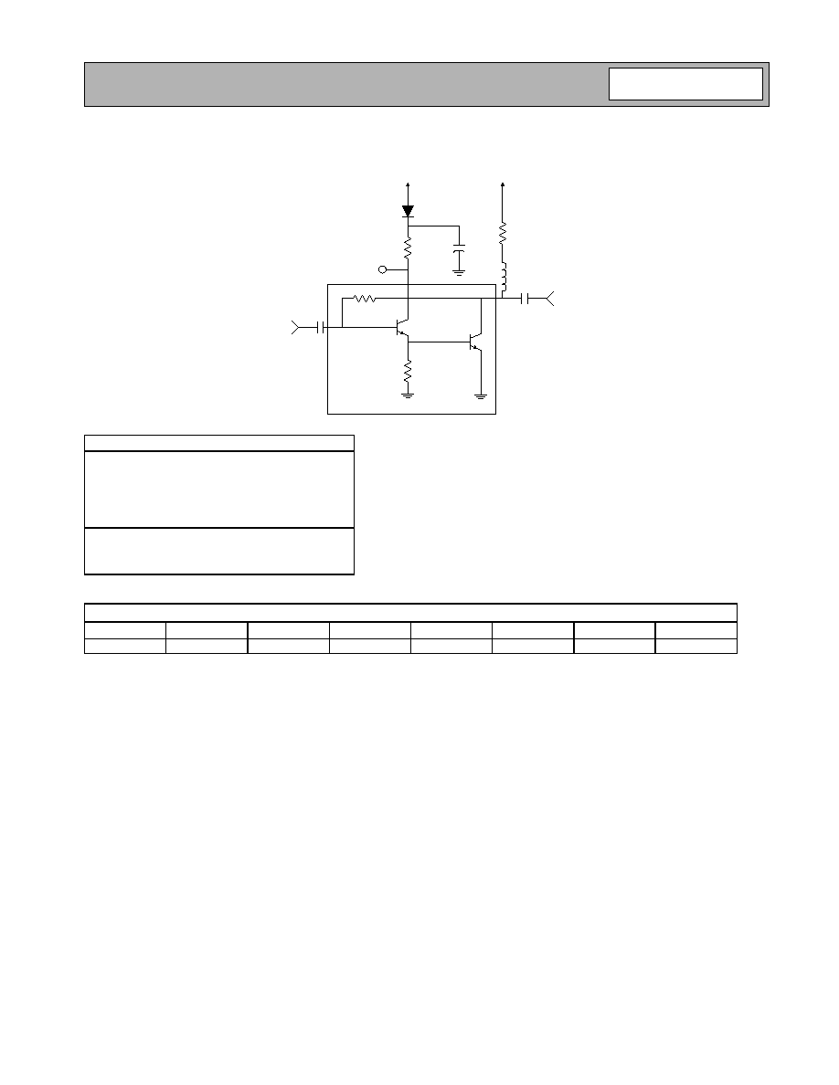
Typical Bias Configuration
Application notes related to biasing circuit, device footprint, and thermal considerations are available on request.
Bias Resistor Selection
R
CC1
:
For 4.7V<V
CC1
<5.0V
R
CC1
=0
For 5.0V<V
CC1
<10.0V
R
CC1
=V
CC1
-4.7/0.029
R
CC2
:
For 5.0V<V
CC2
<10.0V
R
CC1
=V
CC2
-2.98/0.036
Typical Bias Parameters for V
CC1
=V
CC2
=10V:
V
CC1
(V)
V
CC2
(V)
I
CC1
(mA)
V
C1
(V)
R
CC1
(
)
I
CC2
(mA)
V
C2
(V)
R
CC2
(
)
10
10
29
4.75
180
36
2.98
195
In
Out
R
CC2
120
Q1
Q2
V
C1
R
CC1
120
D1,
Blocking Diode
C1
1 uF
V
CC1
V
CC2
Simplified Schematic of Distributed Amplifier

4-116
NDA-410-D
Rev A5 030912
NO
T
FOR
N
EW
DE
SI
GNS
Se
e Up
gr
aded Pr
od
uc
t N
BB-300-
D
Chip Outline Drawing - NDA-410-D
Chip Dimensions: 0.027" x 0.022" x 0.004"
Sales Criteria - Unpackaged Die
Die Sales Information
∑ All segmented die are sold 100% DC-tested. Testing parameters for wafer-level sales of die material shall be nego-
tiated on a case-by-case basis.
∑ Segmented die are selected for customer shipment in accordance with RFMD Document #6000152 - Die Product
Final Visual Inspection Criteria
1
.
∑ Segmented die has a minimum sales volume of 100 pieces per order. A maximum of 400 die per carrier is allow-
able.
Die Packaging
∑ All die are packaged in GelPak ESD protective containers with the following specification:
O.D.=2"X2", Capacity=400 Die (20X20 segments), Retention Level=High(X8).
∑ GelPak ESD protective containers are placed in a static shield bag. RFMD recommends that once the bag is
opened the GelPak/s should be stored in a controlled nitrogen environment. Do not press on the cover of a closed
GelPak, handle by the edges only. Do not vacuum seal bags containing GelPak containers.
∑ Precaution must be taken to minimize vibration of packaging during handling, as die can shift during transit
2
.
Package Storage
∑ Unit packages should be kept in a dry nitrogen environment for optimal assembly, performance, and reliability.
∑ Precaution must be taken to minimize vibration of packaging during handling, as die can shift during transit
2
.
Die Handling
∑ Proper ESD precautions must be taken when handling die material.
∑ Die should be handled using vacuum pick-up equipment, or handled along the long side with a sharp pair of twee-
zers. Do not touch die with any part of the body.
∑ When using automated pick-up and placement equipment, ensure that force impact is set correctly. Excessive force
may damage GaAs devices.
0.022 ± 0.001
[0.57 ± 0.03]
0.027 ± 0.001
[0.68 ± 0.03]
0.004 ± 0.001
[0.10 ± 0.03]
GND
OUTPUT
GND
VIA
GND
VIA
INPUT
VCC1
GND
GND

4-117
NDA-410-D
Rev A5 030912
NO
T
FOR
N
EW
DE
SI
GNS
Se
e Up
gr
aded Pr
od
uc
t N
BB-300-
D
Die Attach
∑ The die attach process mechanically attaches the die to the circuit substrate. In addition, the utilization of proper die
attach processes electrically connect the ground to the trace on which the chip is mounted. It also establishes the
thermal path by which heat can leave the chip.
∑ Die should be mounted to a clean, flat surface. Epoxy or eutectic die attach are both acceptable attachment meth-
ods. Top and bottom metallization are gold. Conductive silver-filled epoxies are recommended. This procedure
involves the use of epoxy to form a joint between the backside gold of the chip and the metallized area of the sub-
strate.
∑ All connections should be made on the topside of the die. It is essential to performance that the backside be well
grounded and that the length of topside interconnects be minimized.
∑ Some die utilize vias for effective grounding. Care must be exercised when mounting die to preclude excess run-out
on the topside.
Die Wire Bonding
∑ Electrical connections to the chip are made through wire bonds. Either wedge or ball bonding methods are accept-
able practices for wire bonding.
∑ All bond wires should be made as short as possible.
Notes
1
RFMD Document #6000152 - Die Product Final Visual Inspection Criteria. This document provides guidance for die
inspection personnel to determine final visual acceptance of die product prior to shipping to customers.
2
RFMD takes precautions to ensure that die product is shipped in accordance with quality standards established to min-
imize material shift. However, due to the physical size of die-level product, RFMD does not guarantee that material will
not shift during transit, especially under extreme handling circumstances. Product replacement due to material shift will
be at the discretion of RFMD.