BP5311A / BP5311XA
The BP5311A and BP5311XA are DC / DC converters for supplying power to liquid crystal display (LCD) panels.
The modules supply a positive voltage for LCDs from a logic circuit power supply (+5). They are available in a
single in-line package as an upright (BP5311A) or L-shaped lead (BP5311XA) type.
Applications
LCD panels in personal computers and word processors.
Features
1) High conversion efficiency
2) Built-in protection circuit
3) Built-in ON/OFF switch.
4) Compact and light.
5) Surface mounting is possible because parts are concentrated on one side.
6) Available as an upright or L-shaped lead type.
DC / DC converter for LCDs
Absolute maximum ratings (Ta=25
∞
C)
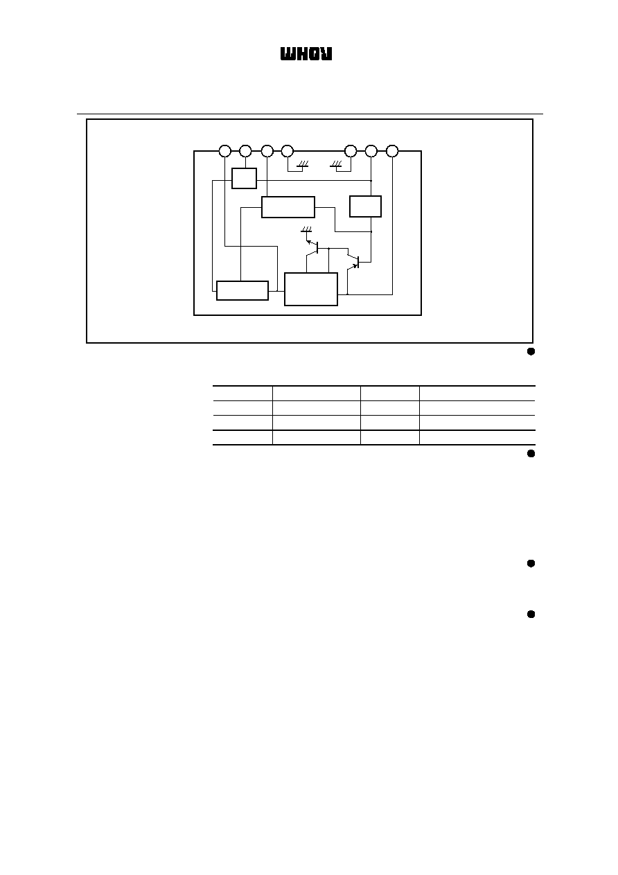
Block diagram
Parameter
Symbol
Limits
Unit
Power supply voltage
V
IN
7
V
Operating temperature range
Topr
∞
C
Storage temperature range
Tstg
∞
C
0~60
-
30~
+
85
SW CTRL
ON / OFF
TRANSFORMER
CURRENT
SENSOR
V
IN
GND
V
CTL
GND
Vref
V
OUT
Co
4
9
8
7
3
2
1
CONTROL
CIRCUIT
1/4

BP5311A / BP5311XA
Pin descriptions
Electrical characteristics
(unless otherwise noted, Ta=25
∞
C, V
CTL
=5V, R1~R2 resistors are disconnected)
Measurement circuit / Application example
Pin name
1
2
V
OUT
Output pin.
3
Vref
Output voltage adjustment pin for contrast ; output
voltage is adjusted by connecting a resistor between
pins 2 and 3 or pins 3 and 4.
GND
Ground pin.
8
9
V
IN
4, 7
V
CTL
Co
Pin No.
Function
Output ON/OFF control pin ; output starts when the
pin is HIGH level, and stops when the pin is LOW
or OPEN.
Input pin ; connect a low-impedance capacitor with
a recommended capacitance of 100
µ
F between
this pin and GND.
Output smoothing capacitor connection pin ; connect
a low-impedance capacitor with a recommended
capacitance of 47
µ
F between this and GND.
Parameter
Symbol
Min.
Typ.
Max.
Unit
Conditions
Input voltage
V
IN
4.5
5.0
5.5
V
Output current
I
OUT
-
-
25
mA
Output voltage
V
OUT
1
28.0
29.5
31.0
V
Output voltage when OFF
V
OUT
2
-
-
0.3
V
Ripple noise voltage
-
100
200
mV
P-P
Efficiency
67
77
-
%
ON / OFF CTL voltage
when ON
V
CTL
1.5
-
-
V
V
CTL
-
-
0.5
V
(Alternatively, when OPEN)
I
CTL
-
-
500
µ
A
Current consumption
when OFF
-
-
50
µ
A
ON / OFF CTL voltage
when OFF
ON / OFF CTL current
I
OFF
Measured with a band width of 20 MHz.
V
IN
=5V, V
CTL
=0V
V
IN
=5V, V
CTL
=1.5V
V
IN
=5V, Vo
<
0.3V
V
IN
=5V, Vo
>
28V
V
IN
=5V, I
OUT
=20mA
V
IN
=5V, I
OUT
=20mA
V
IN
=4.5~5.5V, V
CTL
=0V
V
IN
=4.5~5.5V, I
OUT
=0~25mA
-
-
1
+
C2
R1
R2
V
OUT
GND
1
2
3
4
7
8
9
+
C1
V
CTL
V
IN
GND
BP5311A / BP5311XA
C1 : 100
µ
F / 16V (Low impedance)
C2 : 47
µ
F / 35V (Low impedance)
R1, 2 : Resistors for adjusting output voltage (Contrast adjustment)
Fig.1
2/4
Be sure to use
fuse for safety
BP5311A / BP5311XA
Electrical characteristic curves
(1) Place I/O external capacitors as near as possible to the connection pins. In particular, make sure to
minimize the impedance between the input-side capacitor (C1) and pin 9. A length less than 50 mm is
recommended for a copper foil of 1.0 mm wide and 35
µ
m thick.
(2) Avoid frequent switching using the ON/OFF CTL pin (five times per second at the maximum).
(3) R1 and R2 resistors, which are used for changing the output voltage, are usually not required.
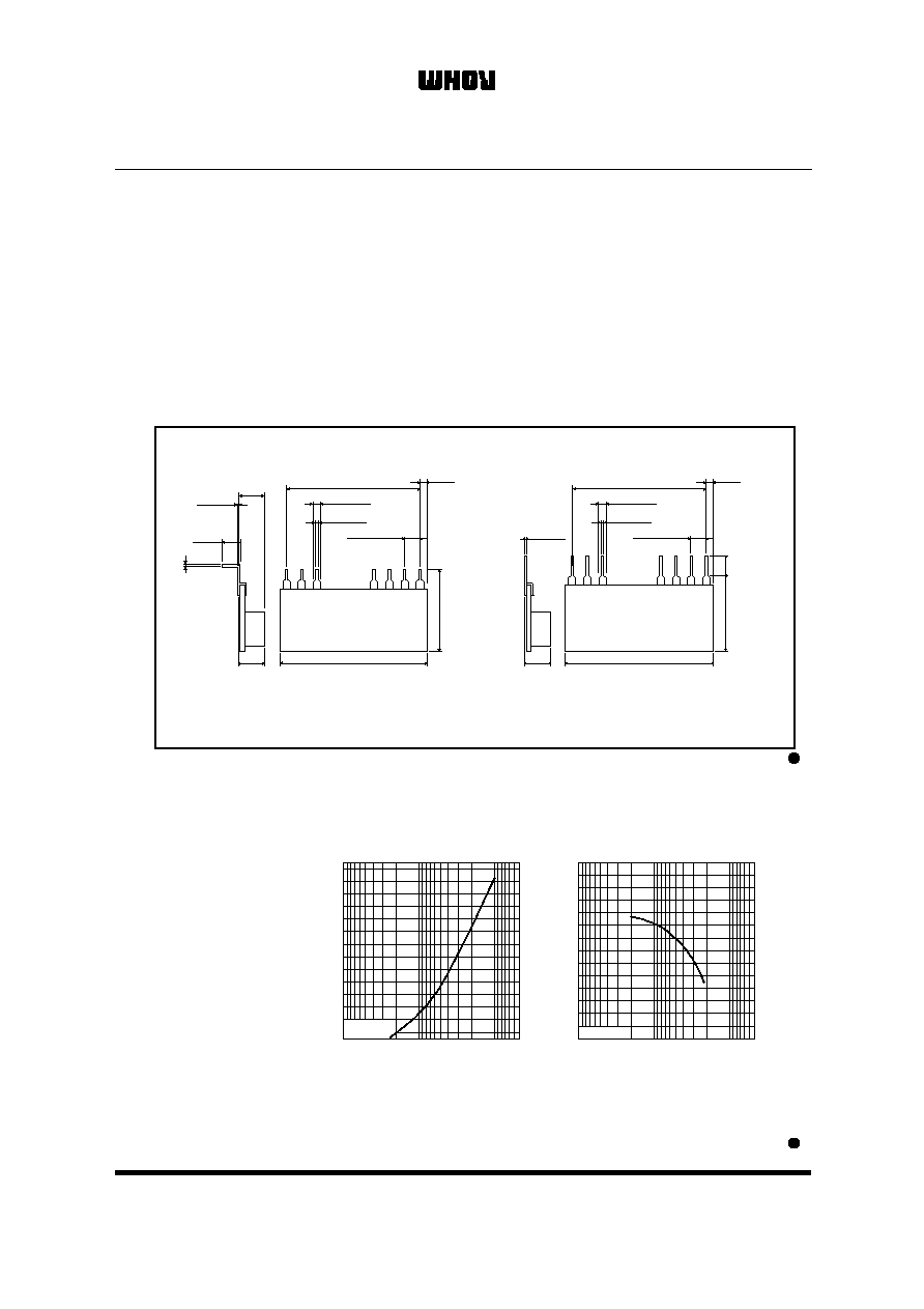
External dimensions (Units : mm)
100k
1M
10M
30
35
OUTPUT VOLTAGE : Vo (V)
V
IN
=5V
FEED BACK RESISTANCE : R1 (
)
Fig.2
Output voltage vs.
feedback resistance (R1)
100k
1M
10M
FEED BACK RESISTANCE : R2 (
)
OUTPUT VOLTAGE: Vo (V)
15
20
25
V
IN
=5V
Fig.3
Output voltage and
feedback resistance (R2)
0.25
±
0.05
6.0 Max.
26.0 Max.
3
±
0.5
14.7 Max.
1
2
3
4
7
8
9
BP5311A
BP5311XA
0.25
±
0.05
1.3
±
0.2
0.5
±
0.1
P=2.54
±
0.2
1.3
±
1.2
2.54
◊
8=20.32
1.3
±
0.2
0.5
±
0.1
P=2.54
±
0.2
1.3
±
1.2
2.54
◊
8=20.32
6.0 Max.
26.0 Max.
15.5 Max.
1
2
3
4
7
8
9
4.5
±
1.0
5.5Max.
0.5Max.
SIP9 (L forming)
SIP9
Unmarked side
Unmarked side
Marked
side
Marked
side
3/4

Precautions on Use of ROHM Power Module
1) The products are designed and produced for application in ordinary electronic equipment (AV equipment,
OA equipment, telecommunication equipment, home appliances, amusement equipment etc.).
If the products are to be used in devices requiring extremely high reliability (medical equipment, transport
equipment, aircraft/spacecraft, nuclear power controllers, fuel controllers, car equipment including car
accessories, safety devices, etc.) and whose malfunction or operational error may endanger human life
and sufficient fail-safe measures, please consult with the Company's sales staff in advance. If product
malfunctions may result in serious damage, including that to human life, sufficient fail-safe measures
must be taken, including the following:
[a] Installation of protection circuits or other protective devices to improve system safety
[b] Installation of redundant circuits in the case of single-circuit failure
2) The products are designed for use in a standard environment and not in any special environments.
Application of the products in a special environment can deteriorate product performance. Accordingly,
verification and confirmation of product performance, prior to use, is recommended if used under the
following conditions:
[a] Use in various types of liquid, including water, oils, chemicals, and organic solvents
[b] Use outdoors where the products are exposed to direct sunlight, or in dusty places
[c] Use in places where the products are exposed to sea winds or corrosive gases, including
Cl2, H2S, NH3, SO2, and NO2
[d] Use in places where the products are exposed to static electricity or electromagnetic waves
[e] Use in proximity to heat-producing components, plastic cords, or othe flammable items
[f] Use involving sealing or coating the products with resin or other coating materials
[g] Use involving unclean solder or use of water or water-soluble cleaning agents for cleaning after
soldering
[h] Use of the products in places subject to dew condensation
3) The products are not radiation resistant.
4) The Company is not responsible for any problems resulting from use of the products under conditions not
recommended herein.
5) The Company should be notified of any product safety issues. Moreover, product safety issues should be
periodically monitored by the customer.
Safety Precautions
1) If change is made to the constant of an external circuit, allow a sufficient margin due to variations of the
characteristics of the products and external components, including transient characteristics, as well as
static characteristics. Please be informed that the Company has not conducted investigations on whether
or not particular changes in the application examples or external circuits would result in the infringement
of patent rights of a third party.
2) The application examples, their constants, and other types of information contained herein are applicable
only when the products are used in accordance with standard methods.
Therefore, if mass production is intended, sufficient consideration to external conditions must be made.
Precautions Regarding Application Example and External Circuits
1) These Specifications contain information related to the Company's industrial property. Any use of them
other than pertaining to the usage of appropriate products is not permitted. Duplication of these
Specifications and its disclosure to a third party without the Company's permission is prohibited.
2) Information and data on products, including application examples, contained in these specifications are
simply for reference; the Company does not guarantee any industrial property rights, intellectual property
rights, or any other rights of a third party regarding this information or data. Accordingly, the Company
does not bear any responsibility for:
[a] infringement of the intellectual property rights of a third party
[b] any problems incurred by the use of the products listed herein.
3) The Company prohibits the purchaser of its products to exercise or use the intellectual property rights,
industrial property rights, or any other rights that either belong to or are controlled by the Company, other
than the right to use, sell, or dispose of the products.
Prohibitions Regarding Industrial Property
4/4