IA3008-CB20A
Contact image sensor heads
Color image sensor head (300dpi)
IA3008-CB20A
The IA3008-CB20A is a color image sensor head that uses LED chips of the three colors red, green, and blue. Through
the use of ROHM's further improvements in optical technologies and LSI circuit designing, the IA3008-CB20A provides
excellent color reproducibility and noise resistance and has taken its place as the industry's highest level compact and
lightweight image sensor head.
!
!
!
!Applications
Color scanners
Multi-function printers (MFPs)
Image scanning devices
!
!
!
!Features
1) Each sensor IC is equipped with a built-in amplifier for greatly increased noise resistance.
2) Red, green, and blue LED chips are used for the light source to obtain excellent color reproducibility.
3) Uses a single power supply operational amplifier. Operation requires only a single 5V power supply.
4) Uses a ceramic board as the base board for excellent dimensional stability, and excellent stability in optical
characteristics.
!
!
!
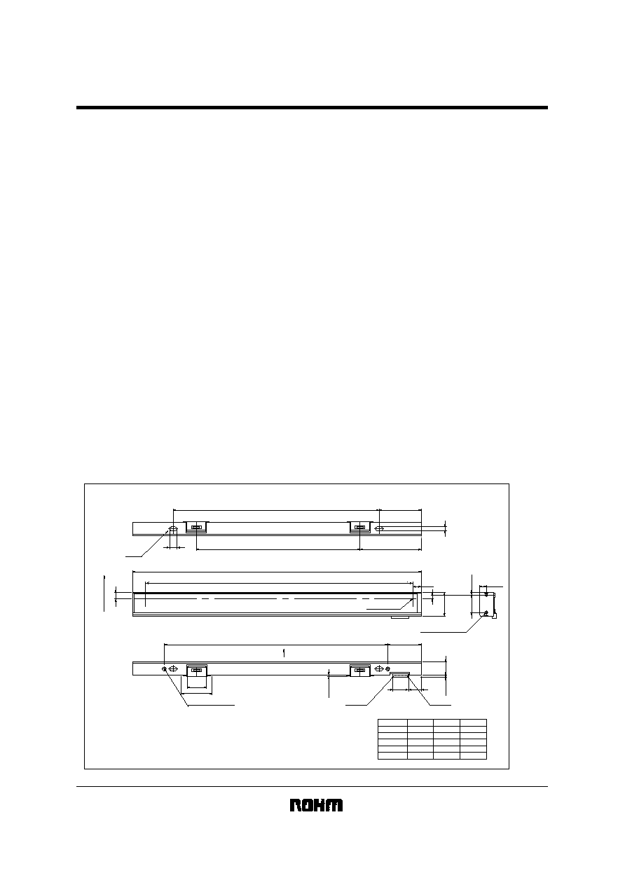
!External dimensions
(Units : mm)
234.4
0.0
-
0.4
27.25
+
0.05
-
0.25
218.8 (Effective Reading Width : 216mm)
Effective Depth 0.5
8
-
R1.5
5
(10.4)
34.25
+0.05
-
0.25
(12.9)
5.5±0.5
7±0.5
1.9±0.1
3.1±0.5
14.2±0.1
19.05
10.6
3
181.15
(133)
49.75
167.15
L
C
(15.5)
(25)
Max. 1.5
6
2
-
R1.5
Max. 2
No.9
No.1
A
±0.3
No.1 Pixel
Effective Depth 7
4
-
1.9
Direction
Paper Feed
Effective Depth 2
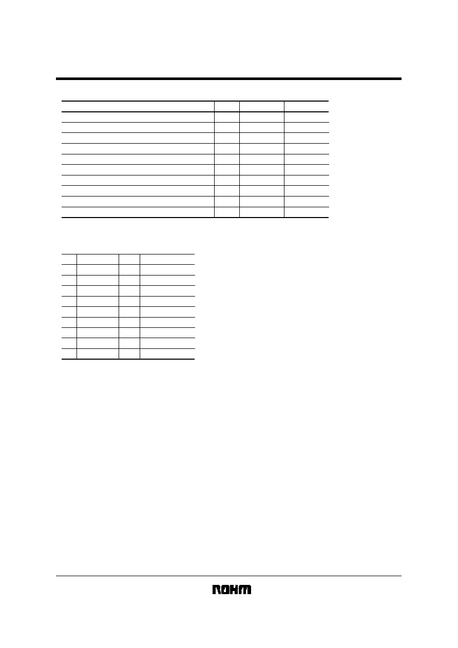
SI
Pin No.
No.8
No.9
CLK
No.1
No.2
No.3
No.4
No.5
R-GND
G-GND
B-GND
No.6
VLED
No.7
Signal
Pin No.
Signal
Ao
GND
V
DD
Note : Deflection at the top of glass : 0~0.25 projection to platen is positive.
(Connector Parts Number)
Socket Housing: IL-Z-9S-S125C3 (JAE)
Socket Contact: IL-Z-C3-A-15000 (JAE)

IA3008-CB20A
Contact image sensor heads
!Timing chart
(a) CLK Timing Chart
ts
tHOLD
tSETUP
tw1
1/fCLK
CLK
tw2
0
1
11
12
13
SI
Ao
1 pixel
2 pixel
Fig.1
(b) Data Output Timing Chart
After turning on the SI pulse, the analog output shape starts from the setting down point of 12CLK pulse.
CLK
0
Note) The CLK section area which is over the effective pixel numbers
(Output blank part) cannot be used as the analog Output standard level.
2
4
6
8
10
12
14
16
SI
Ao