LA-401 D / N Series
LED displays
Rev.B 1/2
Single Digit LED Numeric Display
LA-401 D / N Series
LA-401 D / N series is developed because of the
demand for small single digit LED Numeric Display.
Materials of emission are GaAsP on GaP, AlGalnP GaP
and GaN. This is the height of a letter 10.16mm, single
digit LED Numeric Display that is packed by EPOXY
resin.
Features
1) The height of a letter is 10.16mm.
2) Dimension is 9.6
◊
13.0
◊
7.0mm.
3) The package of surface color is black. Color of
segment is colored in emitting color. (Blue color is only
milky white)
4) Each color has anode common and cathode common
respectively.
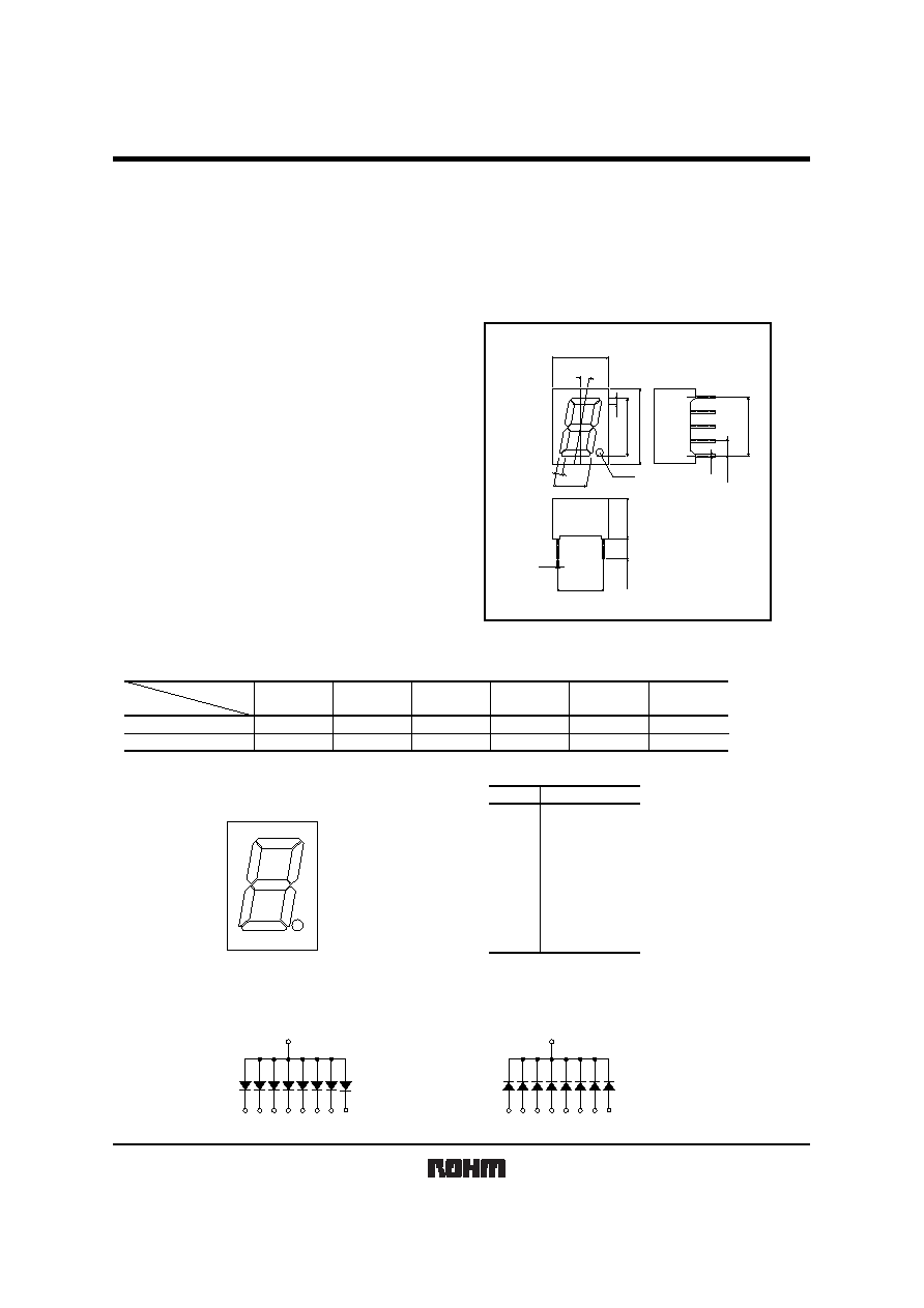
External dimensions (Unit : mm)
10∞
13.0
10.16
1.0
1.0
0.5
(10.16)
0.25
(7.62)
7.0
3.5Min.
5.57
9.6
1.0
(2.54)
Tolerance are
±
0.2 unless otherwise noted:
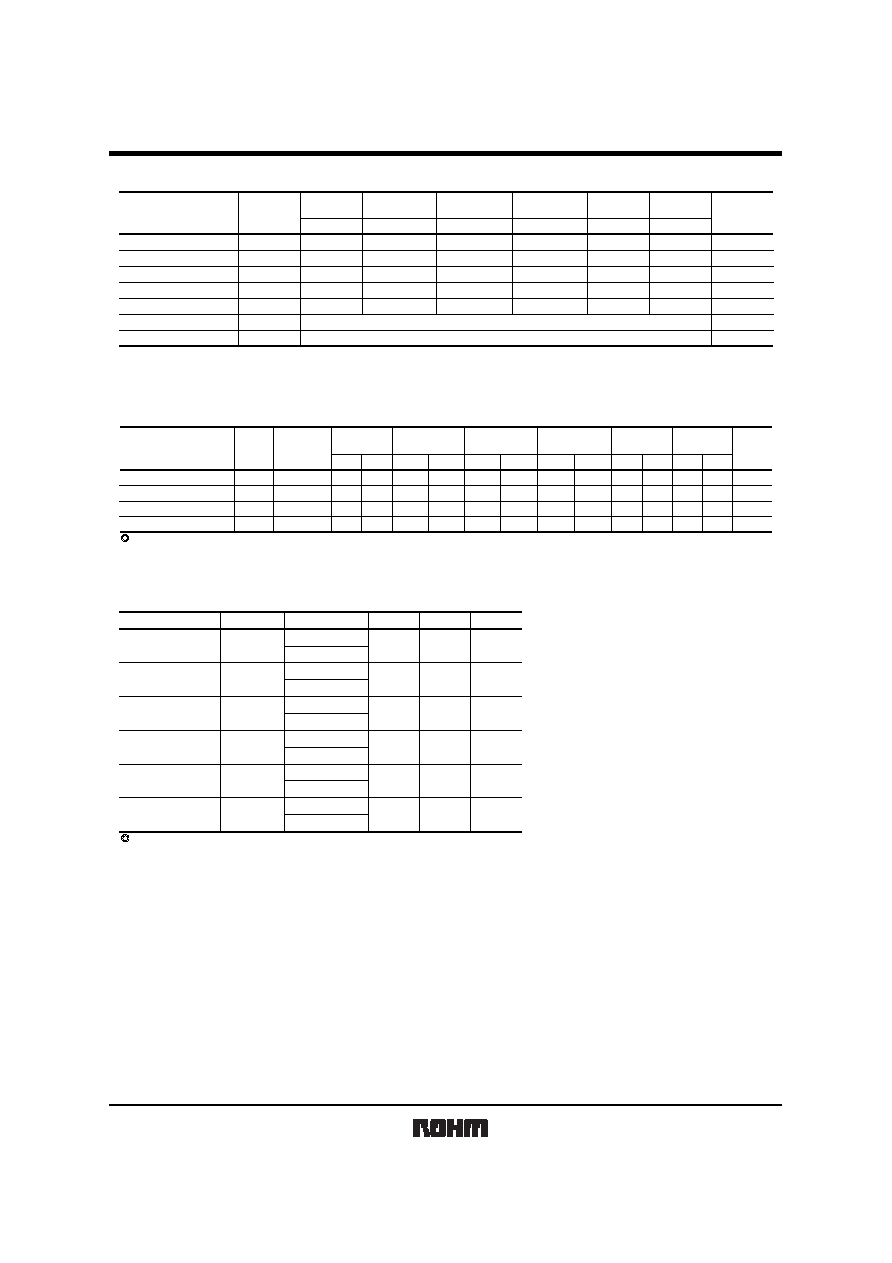
Selection guide
Anode
Cathode
Emitting color
Common
Red
LA-401VD
LA-401VN
Red
High brightness
LA-401AD
LA-401AN
Orange
High brightness
LA-401ED
LA-401EN
Yellow
High brightness
LA-401XD
LA-401XN
Green
LA-401MD
LA-401MN
Blue
LA-401BD
LA-401BN
Pin assignments
Pin No.
1
+
2
+
3
+
4
+
5
10
9
8
7
6
+
+
+
+
+
+
a
g
d
f
b
e
c
D.P
Function
Pin No.
1
2
3
4
5
6
7
8
9
10
Common
Segment "f"
Segment "g"
Segment "e"
Segment "d"
Common
D.P
Segment "c"
Segment "b"
Segment "a"
Equivalent circuit (anode common) (cathode common)
COM
1,6
a
10
b
9
c
8
d
5
e
4
f
2
g
3
D.P
7
COM
1,6
a
10
b
9
c
8
d
5
e
4
f
2
g
3
D.P
7

Appendix
Appendix1-Rev1.1
The products listed in this document are designed to be used with ordinary electronic equipment or devices
(such as audio visual equipment, office-automation equipment, communications devices, electrical
appliances and electronic toys).
Should you intend to use these products with equipment or devices which require an extremely high level of
reliability and the malfunction of with would directly endanger human life (such as medical instruments,
transportation equipment, aerospace machinery, nuclear-reactor controllers, fuel controllers and other
safety devices), please be sure to consult with our sales representative in advance.
Notes
No technical content pages of this document may be reproduced in any form or transmitted by any
means without prior permission of ROHM CO.,LTD.
The contents described herein are subject to change without notice. The specifications for the
product described in this document are for reference only. Upon actual use, therefore, please request
that specifications to be separately delivered.
Application circuit diagrams and circuit constants contained herein are shown as examples of standard
use and operation. Please pay careful attention to the peripheral conditions when designing circuits
and deciding upon circuit constants in the set.
Any data, including, but not limited to application circuit diagrams information, described herein
are intended only as illustrations of such devices and not as the specifications for such devices. ROHM
CO.,LTD. disclaims any warranty that any use of such devices shall be free from infringement of any
third party's intellectual property rights or other proprietary rights, and further, assumes no liability of
whatsoever nature in the event of any such infringement, or arising from or connected with or related
to the use of such devices.
Upon the sale of any such devices, other than for buyer's right to use such devices itself, resell or
otherwise dispose of the same, no express or implied right or license to practice or commercially
exploit any intellectual property rights or other proprietary rights owned or controlled by
ROHM CO., LTD. is granted to any such buyer.
Products listed in this document are no antiradiation design.
About Export Control Order in Japan
Products described herein are the objects of controlled goods in Annex 1 (Item 16) of Export Trade Control
Order in Japan.
In case of export from Japan, please confirm if it applies to "objective" criteria or an "informed" (by MITI clause)
on the basis of "catch all controls for Non-Proliferation of Weapons of Mass Destruction.