 | –≠–ª–µ–∫—Ç—Ä–æ–Ω–Ω—ã–π –∫–æ–º–ø–æ–Ω–µ–Ω—Ç: TCA0J156K | –°–∫–∞—á–∞—Ç—å:  PDF PDF  ZIP ZIP |

TC series
Tantalum capacitors
Rev.A
1/13
Chip tantalum capacitors
TC Series
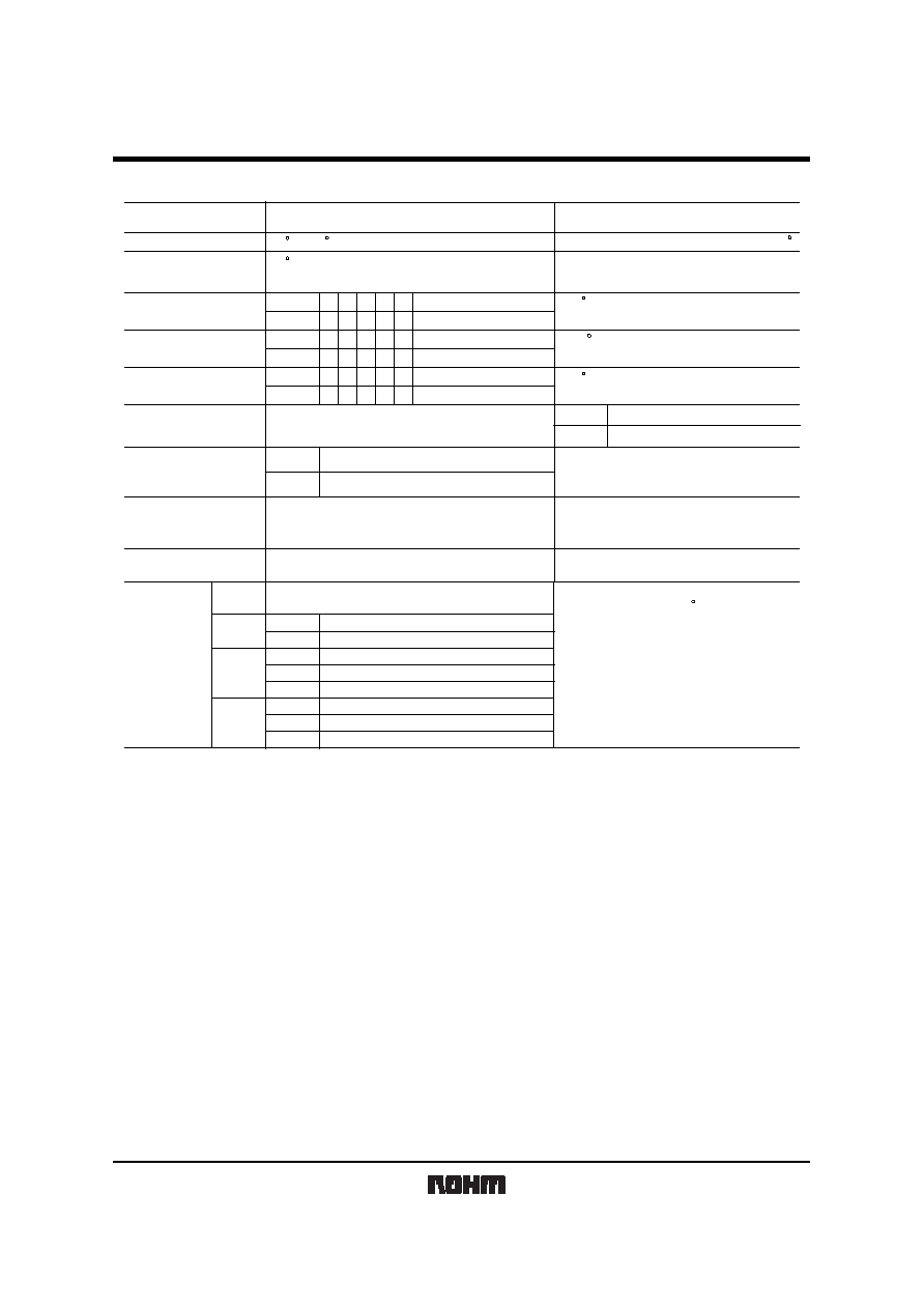
Features ( M )
External dimensions (Unit : mm)
Newly designed ROHM original CSP
structure ( face-down terminal ) provides,
1) Excellent adhesion.
M case
Dimensions
L
H
S
W
2
W
1
(Unit : mm)
Anode mark
L
W
1
H
W
2
S
S
0.5 0.1
+
-
0.8 0.1
+
-
0.55 0.1
+
-
0.85 0.1
+
-
1.6 0.1
+
-
2) Easy visual recognition of fillets.
3) Expanded capacitance range with Low ESR.
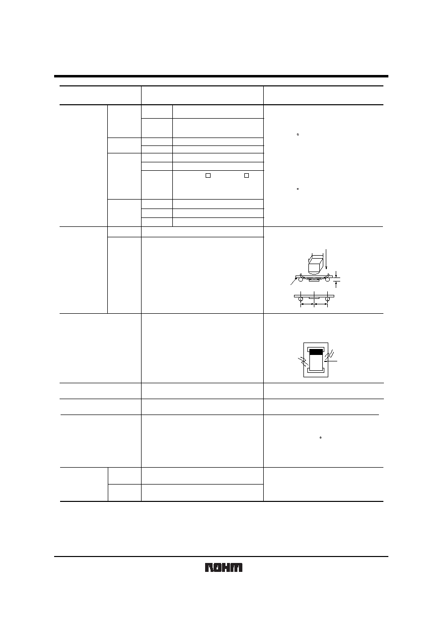
Features ( P , A )
External dimensions (Unit : mm)
1) Vital for all hybrid integrated circuits
board application.
P case
Dimensions
L
H
S
W
2
W
1
Max.1.20
S
S
W
H
L
W
Anode mark
2
1
(Unit : mm)
2.0 0.2
+
-
3.2 0.2
+
-
1.6 0.2
+
-
1.2 0.2
+
-
1.6 0.2
+
-
0.8 0.3
+
-
0.9 0.2
+
-
1.25 0.2
+
-
0.45 0.3
+
-
A case
+
-
2) Wide capacitance range.
3) Screening by thermal shock.
Model name configuration
Case style
Series name
Capacitance tolerance
Capacitance tolerance
Rated voltage (V)
10
0J
1A
0G
Code
Rated voltage
M
6.3
4
K
Code
Nominal capacitance
R : Positive electrode
on the side opposite
to sprocket hole
8 : Tape width
M
1
A
8
R
T
4
7
5
C
16
20
25
1C
1D
1E
Nominal capacitance in pF in
3 digits: 2 significant figures
followed by the figure
repesenting the nymber of 0's.
M
20%
+
-
10%
+
-

TC series
Tantalum capacitors
Rev.A
2/13
Rated Table. Marking
A
E
J
N
S
W
a
e
j
n
s
w
µ
F
Raited voltage (V.DC)
4
0G
1.0
M,P,A
P,A
P,A
1.5
A
2.2
M,P,A
P,A
P
P
M,P
A
3.3
P,A
P
P
P,A
A
4.7
M,P,A M,P,A M,P,A
A
A
A
A
A
A
A
A
6.8
P,A
10
M,P,A
M,P,A
W,P,A
M,P,A
P,A
P,A
A
A
15
P,A
P,A
A
A
22
A
33
A
A
A
47
68
A
A
6.3
0J
10
1A
16
1C
20
1D
25
1E
j J
j a
Voltge code
Voltge code
Capacitance code
Capacitance code
Voltge code
j a
Capacitance code
M case
(1608)
P case
(2012)
Acase
(3216)
TC series
Tantalum capacitors
Rev.A
3/13
Characteristics
Item
Performance
Test conditions
(based on JIS C 5101
-
1 and JIS C 5101
-
3)
Operating Temperature
-
55 C
+
125 C
Maximum operating
temperature with no voltage
derating
+
85 C
Rated voltage
(VDC)
20
16
10
6.3
4
16
10
6.3
4
Category voltage
(VDC)
at 125 C
at 85 C
10
6.3
4
2.5
13
10
6.3
4
2.5
Surge voltage
(VDC)
26
20
20
13
13
8
8
5.2
5.2
DC Leakage current
0.5
µ
F or 0.01CV whichever is greater
Shown in " Standard list "
Tangent of loss angle
(Df, tan
)
Impedance
Appea-
rance
C / C
Df
(tan
)
L.C.
Shall be satisfied the voltage on " Standard list "
Shall be satisfied allowance range.
Shall be satisfied allowance range.
Shall be satisfied the voltage on " Standard list "
at 85 C
M case
M case
M case
M case
M case
M case
Mcase
P, Acase
P, Acase
P,Acase
M case
P,Acase
P, Acase
P,Acase
Voltage reduction when temperature exceeds
+
85 C
Capacitance tolerance
+
1.5~2V.DC
Measuring frequency : 120 12Hz
Measuring voltage : 0.5Vrms
+
-
Measuring circut : DC Equivalent series circuit
+
1.5~2V.DC
Measuring frequency : 120 12Hz
Measuring frequency : 100 10kHz
Measuring voltage : 0.5Vrms
Measuring voltage : 0.5Vrms or less
+
-
+
-
Measuring circut : DC Equivalent series circuit
Resistance to
Soldering heat
There should be nosignificant abnormality.
The indications should be clear.
P case
P case
A case
A case
+
-
Dip in the solder bath
Solder temp : 260 5 C
Duration : 5 0.5s
Repetition : 1
+
-
Ratedvoltage for 5min
Rated voltage for 1min
Less than 200% of initial limit
Less than 200% of initial limit
Less than 150% of initial limit
Less than initial limit
Shall be satisfied the value in Item No.6
Within 20% of initial value
+
-
+
-
20%
+
-
10%,
+
-
20%
10% of initial value
+
-
5% of initial value
+
-

TC series
Tantalum capacitors
Rev.A
4/13
Item
Performance
Test conditions
(based on JIS C 5101
-
1 and JIS C 5101
-
3)
Repetition : 5 cycles
(1 cycle : steps 1~4) without discontinuation.
Temp.
Time
Temperature
cycle
There should be no significant abnormality.
Appea-
rance
C / C
Df
(tan
)
Df
(tan
)
L.C
Moisture
resistance
Appea-
rance
Appea-
rance
C / C
L.C
1
2
3
4
-
55 3 C
Room temp.
125 2 C
Room temp.
30 3min
3min.or less
30 3min
3min.or less
There should be no significant abnormality.
The indications should be
Temperature
Stebility
Temp.
-
55 C
C / C
Df
(tan
)
L.C
-
Temp.
+
85 C
C / C
L.C
5
µ
A or 0.1CV whitchever is greater
C / C
L.C
6.3
µ
A or 0.125CV whitchever is greater
Temp.
+125 C
Df
(tan
)
Shall be satisfied the voltage on " Standard list "
Shall be satisfied the voltage on " Standard list "
M case
M cas
A case
M case
M case
P case
P , A case
P , A case
+
-
P case
A case
M case
M case
P case
P , A case
A casr
M case
P case
A case
M , P case
M , P case
M , P case
M , P case
M case
P case
A case
A case
A case
A case
+
-
+
-
+
-
+
-
Surge
voltage
There should be no significant avnormality.
C / C
L.C
+
-
+
-
+
-
After leaving the sample under such atmospheric
condition that the temperature and humidity are
60 2 C and 90 to 95% RH,respectiveiy,for 500 12h
leave it at room
temperature for 1 to 2h and then measure the
sample.
Shall be satisfied the voltage on " Standard list "
Df
(tan
)
Df
(tan
)
Apply the spesified sergevoltage every 5 0.5 min.
for 30 5 s. each time in the atmospheric condition
of 85 2 C.
Repeat this rocedure 1,000 times.
Less than 200% of initial limit
Less than 200% of initial limit
Less than 200% of initial limit
Less than 200% of initial limit
Less than 150% of initial limit
Less than 150% of initial limit
Less than initial limit
Less than initial limit
Less than initial limit
Shall be satisfied the value in Item No.6
Less than initial limit
Within 20% of initial limit
+
-
Within 20% of initial value
+
-
Within 10% of initial value
+
-
Within 20% of initial limit
+
-
Within 10% of initial limit
15~22
µ
F: within 20% of initial value
+
-
1~10
µ
F: within 10% of initial value
+
-
TCA1A226 , TCA0J476 :
Within 15% of intial value
Others
+
-
Within 10% of initial value
:
+
-
Within 0/
-
15% of initial value
Within
+
15/0 of initial value
Within
+
20/0 of initial value
Within
+
15/0% of initial value
Within 0/
-
12% of initial value
Within
+
12/0% of initial value
Less than 200% of initial limit
Less than initial limit
Less than 200% of initial limit
Less than 150% of initial limit
TC series
Tantalum capacitors
Rev.A
5/13
Item
Performance
Test conditions
(based on JIS C 5101
-
1 and JIS C 5101
-
3)
Loading at
High temperature
Appearance
Appearance
Appearance
M , A case
M case
M case
M case
P case
P case
A case
P case
P , A case
Terminal strength Capacitance The measured value should be stable.
There should nosignificant abnormality.
A force is applied to the terminal until it bends
to 1mm and by a perscribed tool maintain the
condition for5s.(See the figure below)
1mm
F (Apply force)
(Unit : mm)
20
50
R230
45
45
L.C
C / C
Df
(tan
)
Capacitance
3 / 4 or more surface area of the solder coated
terminal dipped in the soldering bath should
be covered with the new solder.
Dip speed=25 2.5mm
/
s
Pre
-
treatment(accelerated aging): Leave
the sample on the boiling distilled water for 1 h.
Solder temp.
Vibration
Measure value shoule not fluctuate during the
measurement.
There should no significant abnormality.
Frequency : 10 to 55 to 10Hz/min.
Amplitude : 1.5mm
Time : 2h each in X and Ydirections
Mounting : The terminal is soldered on a print
circuit board.
.
:
235 5 C
:
2 0.5s
:
H63A
:
Rosin25%
IPA75%
Apply force
a circuit board
product
C105
YAA
Adhesiveness
The terminal should not come off.
Apply force of 5N in the two directions shown
in the figure below for 10 1s after mounting the
terminal on a circuit board.
Dimensions
Refer to "External dimensions"
Measure using a caliper of JISB 7507 Class 2
or higher grade.
The indication should be clear
Dip in the isopropyl alcohol for 30 5s, at room
temperature.
thickness=1.6mm
+
-
+
-
+
-
+
-
+
-
+
-
M , P case : After applying the rated voltage
for 1000
+
36
h without discontinuation via the
serial resistance of 3
or less at a tempera-
ture of 85 2 C, leave the sample at room
temperature / humidity for 1 to 2h and mea-
sure the value.
A case : After applying the rated voltage
for 2000
+
72
h without discontinuation via the
serial resistance of 3
or less at a tempera-
ture of 85 2 C, leave the sample at room
temperature / humidity for 1 to 2h and mea-
sure the value.
+
-
Resistance to solvents
Solderability
Duration
Solder
Flux
+
-
within 15% of initial value
+
-
within 10% of initial value
Others
TCA1A226 , TCA0J476
There should be nosignificant
abnormality.
There should be nosignificant
abnormality. The indications should
be clear.
Less than 200% of initial limit
Less than initial limit
+
-
Within 20% of initial value
+
-
Within 10% of initial value
Less than 200% of initial limit
Less than initial limit
150% of initial limit less than
A case

TC series
Tantalum capacitors
Rev.A
6/13
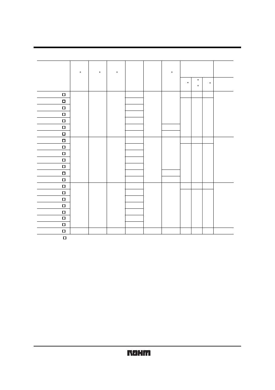
Standard list, TC series
Part No.
22
0.5
4
2.5
5.2
4.7
6.8
0.5
10
TC M 0G 475
TC M 0G 106
TC M 0G 226
TC M 0J 475
TC M 0J 685
4.7
TC M 0J 106
10
0.6
TC M 1A 105
1.0
10
20
6.3
13
2.2
TC M 1A 225
6.3
4
8
0.5
TC M 1A 475
TC M 1C 105
4.7
1.0
0.5
10
16
-
55 C
125 C
25 C
85 C
20
20
20
10
10
30
30
30
15
15
30
30
30
15
15
(
)
9.0
9.0
9.0
13.5
15.0
15.0
20
+
-
20
+
-
20
+
-
20
+
-
< M case : 1608 size >
1.8
=Tolerance (M : )
+
-
20%
Rated
Voltage
85 C
(V)
Category
Voltage
125 C
(V)
Surge
Voltage
85 C
(V)
Cap.
120Hz
(
µ
F)
Tolerance
(%)
Df
120Hz
(%)
Impedance
100kHz
Leakage
Current
25 C
1WV
5min
(
µ
A)
TC series
Tantalum capacitors
Rev.A
7/13
Part No.
Rated
Voltage
85 C
(V)
Cstegory
Voltage
125 C
(V)
Surge
Voltage
85 C
(V)
Cap.
120Hz
(mF)
Tolerance
(%)
Leakage
Current
25 C
1WV.60s
(mA)
Df 120Hz
(%)
TC P 0G 106
TC P 0G 156
10
0.5
15
0.6
TC P 0G 226
TC P 0J 155
22
20,10
0.9
1.5
1.5
TC P 0G 475
TC P 0G 685
4.7
6.8
TC P 0G 225
2.2
TC P 0G 335
3.3
TC P 0J 225
2.2
2.2
TC P 0J 335
TC P 0J 475
4
2.5
5.2
3.3
3.3
4.7
4.7
6.3
10
13
20
4
8
6.8
TC P 0J 685
TC P 0J 106
10
6.8
10
0.5
0.6
0.5
0.5
TC P 0J 156
TC P 1A 105
TC P 1A 155
TC P 1A 225
TC P 1A 335
TC P 1A 475
TC P 1A 685
TC P 1A 106
TC P 1C 105
15
0.9
1.0
1.0
6.3
10
16
20,10
-
55 C
125 C
25 C
85 C
15
10
20
10
20
20
10
10
30
15
30
30
15
15
15
30
15
30
30
15
15
Impedance
100kHz
(
)
27.5
27.5
27.5
27.5
+
-
+
-
+
-
=Tolerance (M : )
+
-
20%,K :
+
-
20,10
20,10
+
-
10%
< P case : 2012 size >

TC series
Tantalum capacitors
Rev.A
8/13
22
0.9
33
1.3
47
68
1.9
2.7
3.3
1.5
4
10
0.5
15
0.6
TC A 0G 475
TC A 0G 106
TC A 0G 156
TC A 0G 226
TC A 0G 336
TC A 0G 476
TC A 0G 686
TC A 0J 335
4.7
TC A 0G 685
6.8
TC A 0J 475
4.7
2.2
TC A 0J 685
TC A 0J 106
2.5
5.2
6.8
3.3
10
4.7
0.5
6.3
13
15
TC A 0J 156
TC A 0J 226
22
3.0
0.5
0.7
TC A 0J 336
TC A 0A 476
TC A 1A 155
TC A 1A 225
TC A 1A 335
TC A 1A 475
TC A 1A 685
33
2.1
0.9
47
6.8
6.3
10
4
8
20,10
-
55 C
125 C
25 C
85 C
10
6
8
10
12
18
6
8
10
12
8
6
18
12
14
30
34
10
12
14
30
10
12
34
8
10
12
16
24
8
10
12
16
8
10
24
(
)
20.0
20.0
20.0
20,10
+
-
+
-
+
-
+
-
20,10
1.0
TC A 1A 106
10
12
10
1.5
TC A 1A 156
15
10
14
12
2.2
TC A 1A 226
22
12
30
16
TC A 1C 105
1.0
0.5
TC A 1C 155
1.5
TC A 1C 225
2.2
6
10
10
20
TC A 1C 335
3.3
16
8
20.0
0.8
TC A 1C 475
4.7
20,10
+
-
20,10
1.1
TC A 1C 685
6.8
0.6
TC A 1C 106
10
8
12
10
13
26
0.5
TC A 1D 105
1.0
20
6
10
8
20.0
< A case : 3216 size >
0.6
1.4
Part No.
Cap.
120Hz
(
µ
F)
Tolerance
(%)
Df
120Hz
(%)
Impedance
100kHz
Leakage
Current
25 C
1WV
5min
(
µ
A)
Surge
Voltage
85 C
(V)
Category
Voltage
125 C
(V)
Rated
Voltage
85 C
(V)
=Tolerance (M : )
+
-
20%,K :
+
-
10%

TC series
Tantalum capacitors
Rev.A
9/13
Packaging specifications
Tape [ M case ]
Reel [ M case ]
Case
M
A 0.1
+
-
B 0.1
+
-
W 0.2
+
-
E 0.1
+
-
F 0.05
+
-
P
1
0.1
+
-
P
2
0.05
+
-
P
0
0.1
+
-
1.0
1.85
8.0
1.75
3.5
4.0
2.0
4.0
Unit : [mm]
13 0.2
60
+
1 0
0 1.5
180
9.0
11.4 1.0
Label sticking position
EIAJ ET
-
7002A
pull direction
+ -
+
1.0 0
+
-
A
B
Sprolet hold
Do
P
1
P
2
P
0
E
F
W
Sprolet hole
Do
t
1
t
2
Pull-out direction
B
A
Tape [ P.A case ]
Reek [ P.A case ]
P1
P2
P3
E
F
W
Component is loadee
Unit : [mm]
13 0.2
60
+
1 0
0
-
1.5
180
9.0
11.4 1.0
Labelsticling position
EIAJ ET
-
7002A
Pull direction
+ -
+
1.0 0
+
-
Case
P
A
A 0.1
+
-
B 0.1
+
-
W 0.1
+
-
E 0.1
+
-
F 0.1
+
-
P
1
0.1
+
-
P
2
0.05
+
-
P
0
0.1
+
-
1.55
1.9
2.3
3.5
8.0
8.0
1.75
1.75
3.5
3.5
4.0
4.0
2.0
2.0
4.0
4.0
Packaging style
4,000pcs
3,000pcs
2,000pcs
Case code
package
Taping
M
P
A
Packaging style
plastic taping
180mmReel
Symbol
R
Basic ordering units

TC series
Tantalum capacitors
Rev.A
10/13
Electrical characteristics and operation notes
(1) Soldering conditions (soldering temperature and soldering time)
130
140
150
160
170
0
60
90
120
150
180
TIME (
sec)
Preheat
Fig.1 reflow soldering
200
220
240
260
280
0
10
20
30
40
50
60
70
TIME (
sec)
Reflow zone
TEMPERATURE ( C)
TEMPERATURE ( C)
200
210
220
230
240
250
260
270
0
2
4
6
8
10
12
14
16
TIME (
sec)
TEMPERATURE ( C)
Fig.2 Flow soldering (Dip wave soldering)
280
300
320
340
0
5
10
15
20
25
TIME (
sec)
Fig.3 Hand soldering (Wattage : 30W MAX.)
TEMPERATURE ( C)
(2) Leakage current-to-voltage ratio
0.01
0.1
1
0
20
40
60
80
100
% OF RATED VOLTAGE (
V
R)
Fig.4
LEALKAGE CURRENT RATIO DCL / DCL
TC series
Tantalum capacitors
Rev.A
11/13
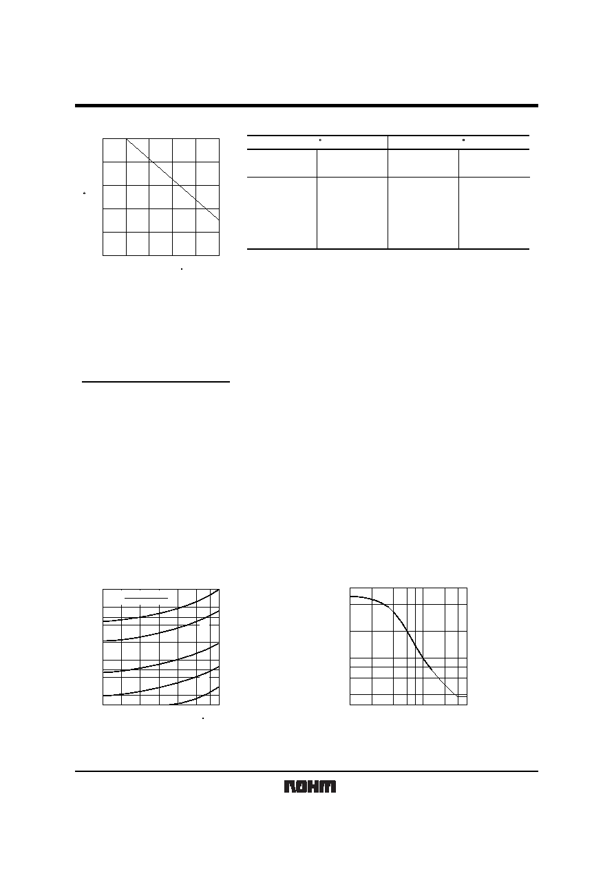
(3) Derating voltage as function of temperature
50
60
70
80
90
100
75
85
95
105
115
125
Fig.5
PERCENT OF 85 C RVDC1 (
V
R)
TEMPERATURE ( C)
Rated Voltage
4
6.3
10
16
20
5.2
8
13
20
26
2.5
4
6.3
10
13
3.4
5
9
12
16
Surge Voltage
Category Voltage
Surge Voltage
(V.DC)
(V.DC)
(V.DC)
(V.DC)
85 C
125 C
(4) Reliability
The malfunction rate of tantalum solid state electrolytic capacitors varies considerably depending on the conditions of
usage (ambient temperature, applied voltage, circuit resistance).
Formula for calculating malfunction rate
p =
b
◊
(
E
◊
SR
◊
Q
◊
CV
)
p
: Malfunction rate stemming from operation
b
: Basic malfunction rate
E
: Environmental factors
SR
: Series resistance
Q
: Level of malfunction rate
CV
: Capacitance
For details on how to calculate the malfunction rate stemming from operation, see the tantalum solid state electrolytic
capacitors column in MIL-HDBK-217.
Malfunction rate as function of operating Malfunction rate as function of circuit resistance (
/V)
temperature and rated voltage
0.01
0.02
0.03
0.06
0.1
0.2
0.3
0.5
1.0
Ratio=
Rated Voltage
Applied Voltage
1.0
0.7
0.5
0.3
0.1
20
40
60
85
Fig.6
FAILURE RATE COEFFICIENT
OPERATING TEMPERATURE ( C)
0.4
0.6
0.8
1.0
2.0
4.0
6.0
0.1
0.2
0.6
0.4
3.0
1.0
2.0
RESISTANCE OF CIRCUIT (
/ V)
Fig.7
RESISTANCE COEFFICIENT (
)
TC series
Tantalum capacitors
Rev.A
12/13
(5) Maximum power dissipation
Warming of the capacitor due to ripple voltage balances with warming caused by Joule heating and by radiated heat.
Maximum allowable warming of the capacitor is to 5
∞
C above ambient temperature. When warming exceeds 5
∞
C, it can
damage the dielectric and cause a short circuit.
Power dissipation (P) = I
2
∑
R
Ripple current
P : As shown in table at right
R : Equivalent series resistance
Notes:
1. Please be aware that when case size is changed, maximum allowable power dissipation is reduced.
2. Maximum power dissipation varies depending on the package. Be sure to use a case which will keep warming within
the limits shown in the table below.
Allowable power dissipation (W) and maximum temperature rising
Case
Temp.
0.070
A case (3216)
0.063
0.056
0.028
0.025
P case (2012)
0.022
0.020
0.010
5
5
5
2
Max. Temp Rise [ C]
+
25 C
+
55 C
+
85 C
+
125 C
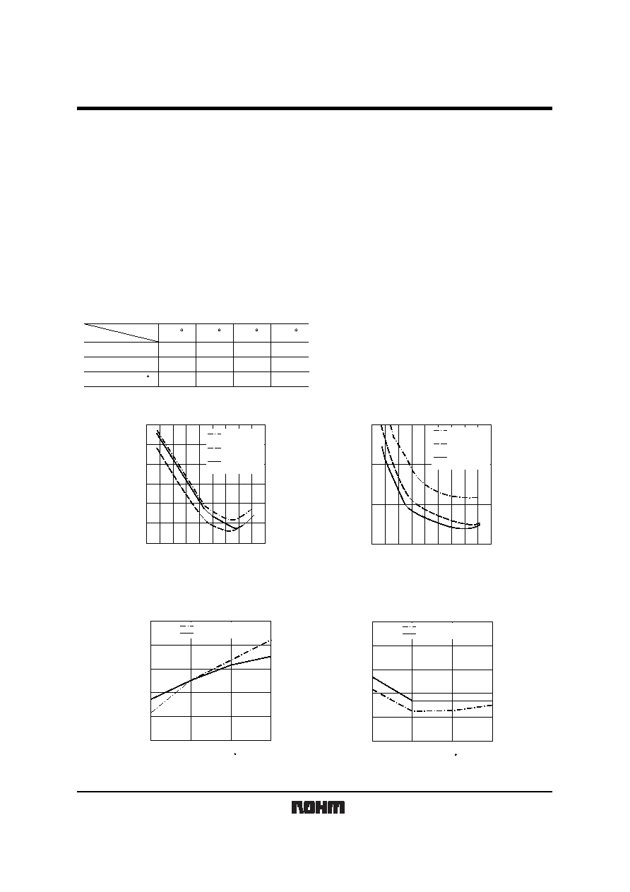
(6) Impedance frequency characteristics (7) ESR frequency characteristics
1
10
100
1000
10000
100000
G475
A case (3216)
C105
A case (3216)
A105
P case (2012)
1
100
10k
1M
500M
100M
FREQUENCY (
Hz)
Fig.10
IMPEDANCE (
)
1
0.1
10
100
G475
A case (3216)
C105
A case (3216)
A105
P case (2012)
1
100
10k
1M
500M
100M
FREQUENCY (
Hz)
Fig.11
ESR (
)
(8) Temperature characteristics
-
10
-
26
-
2
0
2
6
10
-
55
25
CAP 120Hz
85
125
Fig.12
CAP CHANGE (%)
4V
-
4.7
µ
F A case (3216)
10V
-
1
µ
F P case (2012)
TEMPERATURE ( C)
0
1
2
3
4
5
-
55
25
DF 120Hz
85
125
Fig.13
DF (%)
4V
-
4.7
µ
F A case (3216)
10V
-
1
µ
F P case (2012)
TEMPERATURE ( C)

TC series
Tantalum capacitors
Rev.A
13/13
10
100
1000
0
-
55
25
LC 1WV
85
125
Fig.14
LC (
nA)
4V
-
4.7
µ
F A case (3216)
10V
-
1
µ
F P case (2012)
TEMPERATURE ( C)
1
2
3
0
-
55
25
IMPEDANCE 100kHz
85
125
Fig.15
IMPEDANCE (
)
4V
-
4.7
µ
F A case (3216)
10V
-
1
µ
F P case (2012)
TEMPERATURE ( C)
The rush current is in inverse proportion to the ESR.
Rush current
The excessive rush current may cause a damage.
Fig. 16 Max. rush current and ESR
ESR
(100kHz)
33
µ
F
33
µ
F
100
µ
F
tantalum capactior
aluminum electrolysis
4.7
µ
F
4.7
µ
F
100
10
INRUSH CURRENT (A)
1
0.1
0.1
1
10
100
47
µ
F
Vpp=10V llimit=20A
Pulse Width=500
µ
sec.
Power OP Amp Slew Rate=10V/6
µ
s
22
µ
F
15
µ
F
The rush current may be reduced by the protection resistors
Fig. 17 Change in I max by protection resistors
V (V)
100
10
I (A)
1
R
I =
0.476
+
R
V
0.1
0.1
1
10
100
I =
SAMPLE 16V
-
3.3
µ
F
Pulse width=500
µ
sec
Slew rate=10V
-
6
µ
c
Current limit=20A
0.25
1.0
2.0
5.0
0.476
V
R=0
0.5

Appendix
Appendix1-Rev1.1
The products listed in this document are designed to be used with ordinary electronic equipment or devices
(such as audio visual equipment, office-automation equipment, communications devices, electrical
appliances and electronic toys).
Should you intend to use these products with equipment or devices which require an extremely high level of
reliability and the malfunction of with would directly endanger human life (such as medical instruments,
transportation equipment, aerospace machinery, nuclear-reactor controllers, fuel controllers and other
safety devices), please be sure to consult with our sales representative in advance.
Notes
No technical content pages of this document may be reproduced in any form or transmitted by any
means without prior permission of ROHM CO.,LTD.
The contents described herein are subject to change without notice. The specifications for the
product described in this document are for reference only. Upon actual use, therefore, please request
that specifications to be separately delivered.
Application circuit diagrams and circuit constants contained herein are shown as examples of standard
use and operation. Please pay careful attention to the peripheral conditions when designing circuits
and deciding upon circuit constants in the set.
Any data, including, but not limited to application circuit diagrams information, described herein
are intended only as illustrations of such devices and not as the specifications for such devices. ROHM
CO.,LTD. disclaims any warranty that any use of such devices shall be free from infringement of any
third party's intellectual property rights or other proprietary rights, and further, assumes no liability of
whatsoever nature in the event of any such infringement, or arising from or connected with or related
to the use of such devices.
Upon the sale of any such devices, other than for buyer's right to use such devices itself, resell or
otherwise dispose of the same, no express or implied right or license to practice or commercially
exploit any intellectual property rights or other proprietary rights owned or controlled by
ROHM CO., LTD. is granted to any such buyer.
Products listed in this document are no antiradiation design.
About Export Control Order in Japan
Products described herein are the objects of controlled goods in Annex 1 (Item 16) of Export Trade Control
Order in Japan.
In case of export from Japan, please confirm if it applies to "objective" criteria or an "informed" (by MITI clause)
on the basis of "catch all controls for Non-Proliferation of Weapons of Mass Destruction.