 | –≠–ª–µ–∫—Ç—Ä–æ–Ω–Ω—ã–π –∫–æ–º–ø–æ–Ω–µ–Ω—Ç: PM9106APE | –°–∫–∞—á–∞—Ç—å:  PDF PDF  ZIP ZIP |

sames
FEATURES
n
Performs power measurement and di-
rectly drives a 5 digit (7 segment) LED
display
n
Accuracy better than 1% (± 1 count)
n
Protected against ESD
n
Total power consumption rating below
800mW
1/10
n
Uses a shunt resistor or for current
sensing
n
Operates over a wide temperature
range
n
Precision voltage reference on-chip
SINGLE PHASE WATT MEASUREMENT MODULE
WITH A 5 DIGIT LED DISPLAY
4358
PDS038-SA9106-001
REV. A
06-09-1995
SA9106 APPLICATION NOTE
PM9106AP
DESCRIPTION
The SAMES single phase Watt measurement module, the PM9106AP includes an on-
board 5 digit (7 segment) Light Emitting Diode (LED) display. Active power is directly
displayed in watts, with a full scale of 20 000 watts.
The measured power is updated approximately every 2 seconds, giving an average
power reading for this period.
This method of calculation takes the power factor into account.
This innovative universal Watt measurement module is ideally suited for the display of
the measured power in single phase, industrial and domestic power measurement
applications.
The application utlises the SAMES SA9106AP single phase Watt measurement
integrated circuit for power measurement and display.
As a safety measure, this application shows the current sensor connected to the neutral
line. In practice, the live line may be used for current sensing, provided that the supply
connections (MAINS) are reversed on the module.
PM9106AP
2/10
sames
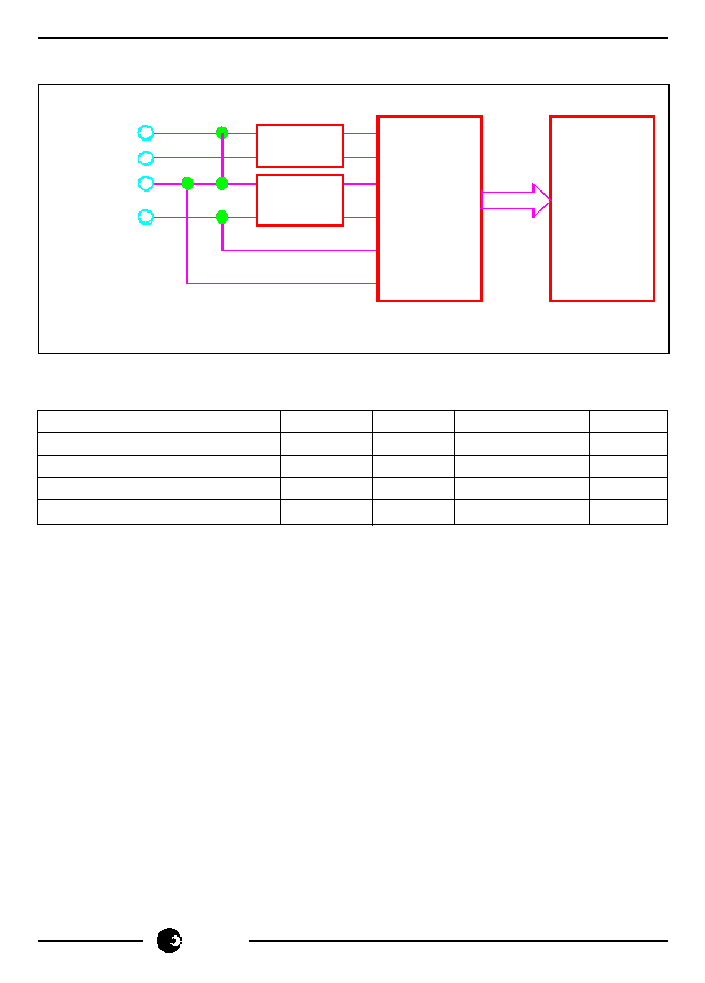
BLOCK DIAGRAM
ABSOLUTE MAXIMUM RATINGS*
Parameter
Symbol
Min
Max
Unit
Supply Voltage (Note 1)
V
AC
540
V
Current Sense Input (Note 1)
V
IV
-2.5
+2.5
V
Storage Temperature
T
STG
-25
+125
∞C
Operating Temperature (Note2)
T
O
-10
+70
∞C
Note 1:
Voltages are specified with reference to Live.
Note 2:
The SA9106AP integrated circuit is specified to operate over the temperature
range -10∞C to +70∞C. The module functionality will however depend upon
the external components used.
*Stresses above those listed under "Absolute Maximum Ratings" may cause permanent
damage to the device. This is a stress rating only. Functional operation of the device
at these or any other conditions above those indicated in the operational sections of this
specification, is not implied. Exposure to Absolute Maximum Ratings for extended
periods may affect device reliability.
NEUTRAL
(Mains)
NEUTRAL IN
NEUTRAL OUT
LIVE
POWER
SUPPLY
SHUNT
SA9106A
WATT
METER
IC
DR-00913
5-DIGIT
LED
DISPLAY

PM9106AP
sames
3/10
FUNCTIONAL DESCRIPTION
1.
Power Calculation
In the Application Circuit (see Figure 2), the output current from the current sensor
will be between 0 and 16µA (0 to 80A through a shunt resistor of 625
µ
). The current
input stage saturates at input currents greater than18µA
RMS
. The mains voltage
(230V + 15% -20%) is used to supply the circuitry with power and for the power
calculation, together with the current information from the current sensor (shunt
resistor).
The SA9106AP integrated circuit may be adjusted to accomodate any voltage or
current values. The method of calculating external component values is described
in paragraph 5 (Circuit Description).
SAMES offers two evaluation module options, namely 230V/80A and 115/80A.
ELECTRICAL CHARACTERISTICS
(Over the temperature range -10∞C to +70∞C, unless otherwise specified.)
Parameter
Symbol
Min
Typ
Max
Unit
Condition
Supply Voltage
V
AC
180
230
265
V
Continuous
operation
Power Consumption
1
800
mW
V
AC
= 230V
Note 1: Power consumption specifications exclude power consumed by the current
sensor.
Note 2: Isolation voltage may be specified, depending on customer requirements.
PIN DESCRIPTION
Designation
Description
MAINS
Voltage supply connection to Neutral line
Voltage supply connection to Live line
NEUTRAL IN
Connection to positive side of current sensor
NEUTRAL OUT
Connection to negative side of current sensor
The calculated power is directly displayed on a 5 digit (7 segment) LED display. The
update interval is approximately every 2 seconds.
PM9106AP
4/10
sames
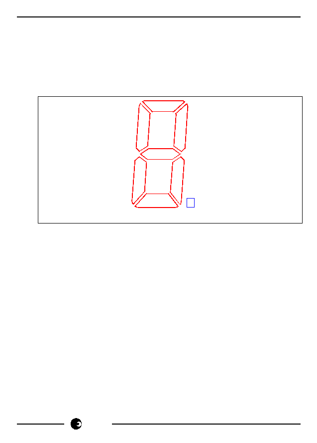
2.
LED Display
The PM9106AP has an on-board LED display comprising 5 (7 segment) common
cathode digits, as well as a sign LED.
The sign LED is addressed by DIG [5], the most significant digit by DIG [4] and the
least significant digit by DIG [0].
The position of the segments a, b, c, d, e, f and g are given in the diagram below:
The full scale power displayed is 20 000 watts. An overflow is indicated by a flashing
display.
3.
Electrostatic Discharge (ESD) Protection
The device's inputs/outputs are protected against ESD according to Mil-Std 883C,
method 3015. The modules resistance to transients will be dependant upon the
protection components used.
4.
Power Consumption
The overall power consumption rating for this power metering application (Figure 2),
is under 800mW, excluding the current sensor.
5.
Circuit Description
The Application Circuit (Figure 2) shows the components required for the Watt
measurement module, using a shunt resistor for current sensing.
c
d
.
e
g
f
DR-00914
a
a
h
.
b

PM9106AP
sames
5/10
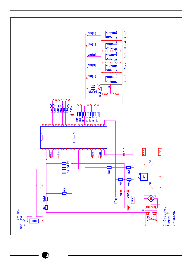
The most important external components for the SA9106AP device are:
C
1
and C
2
are the outer loop capacitors for the two integrated oversampling A/D
converters. The value of these capacitors is 560pF.
The actual values determine signal to noise and stability performance. The optimum
tolerances should be within ± 10%.
C
3
and C
4
are the inner loop capacitors of the A/D converters. The optimum value
is 3.3nF. The actual values are uncritical. Values smaller than 0.5nF and larger than
5nF should be avoided.
R
2
, R
1
and R
SH
are the resistors defining the current level into the current sense input.
The values should be selected for an input current of 16µA
RMS
into the SA9106AP
at rated line current.
Values for RSH of less than 200µ
should be avoided.
R
1
= R
2
= (I
L
/16µA
RMS
) * R
SH
/2
Where
I
L
=
Line current
R
SH
=
Shunt resistor/termination resistor
R
3
, R
5
and R
4
set the current for the voltage sense input. The values should be
selected so that the input current into the voltage sense input (virtual ground) is set
to 14µA.
R
7
defines all on-chip bias and reference currents. With R
7
= 24k
, optimum
conditions are set.
XTAL is a colour burst TV crystal (f = 3.5795MHz) for the oscillator. The oscillator
frequency is divided down to 1.7897MHz on-chip and supplies the A/D converters
and the digital circuitry.
PM9106AP
6/10
sames
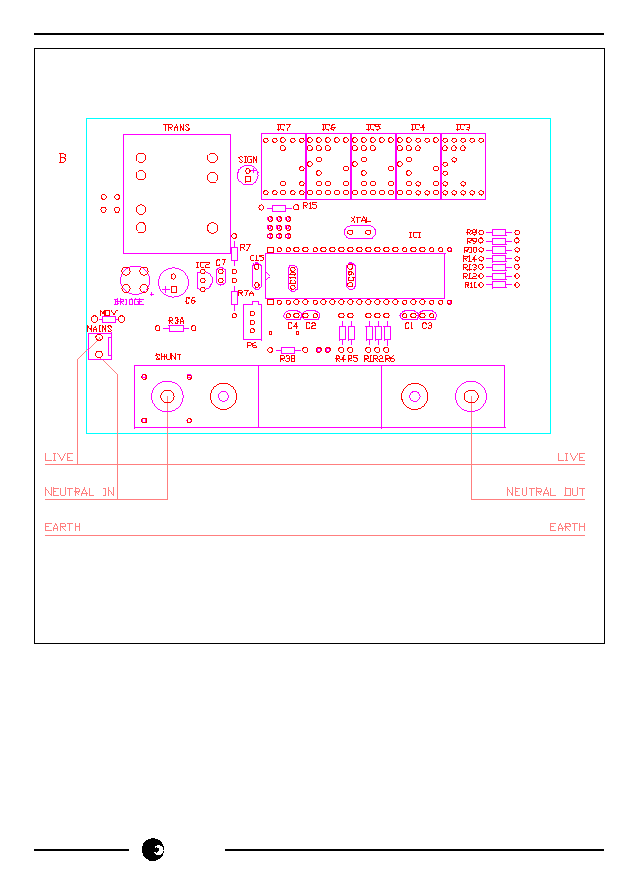
Figure 1: Connection Diagram
D R - 0 0 9 1 5
PM9106AP
sames
7/10
Figure 2: Application Circuit.

PM9106AP
8/10
sames
Parts List for Application circuit: Figure 2
Item Symbol Description
Detail
1
IC-1
SA9106A
DIP-40
2
IC-2
5V 100mA Voltage Regulator
3
IC-3
ELS-511 HWB, Common cathode 7 segment read-out
4
IC-4
ELS-511 HWB, Common cathode 7 segment read-out
5
IC-5
ELS-511 HWB, Common cathode 7 segment read-out
6
IC-6
ELS-511 HWB, Common cathode 7 segment read-out
7
IC-7
ELS-511 HWB, Common cathode 7 segment read-out
8
BR
W04M, Bridge Rectifier
9
SIGN
Red LED, 3mm
diameter, high bright
10
XTAL
Crystal, 3.5795 MHz
Colour burst TV
11
R1
Resistor, 1% metal
Note 1
12
R2
Resistor, 1% metal
Note 1
13
R3A
Resistor, 1% metal
Note 2
14
R3B
Resistor, 1% metal
Note 2
15
R4
Resistor, 1M, 1/4W, 1% metal
16
R5
Resistor, 24k, 1/4W, 1%, metal
17
R7A
Resistor, 820
, 1/4W, 1%, metal
18
R7B
Resistor, 820
, 1/4W, 1%, metal
19
R8
Resistor, 50
(Segment G)
Note 3
20
R9
Resistor, 50
(Segment F)
Note 3
21
R10
Resistor, 50
(Segment E)
Note 3
22
R11
Resistor, 50
(Segment D)
Note 3
23
R12
Resistor, 50
(Segment C)
Note 3
24
R13
Resistor, 50
(Segment B)
Note 3
25
R14
Resistor, 50
(Segment A)
Note 3
26
R1
Resistor, 50
,114W
27
P6
Trimpot, 5k
Multi-turn
28
C1
Capacitor,560pF
29
C2
Capacitor, 560pF
30
C3
Capacitor, 3.3nF
31
C4
Capacitor, 3.3nF
32
C6
Capacitor, 1000µF.16V, Electrolytic
33
C7
Capacitor, 100nF
34
C8
Capacitor, 100nF
35
C9
Capacitor, 100nF
36
C15
Capacitor, 820nF
Note 4
37
TRANS 110V x 2 to 2.7V, 1.5VA Transformer
38
RSH
Shunt Resistor
Note 5

PM9106AP
sames
9/10
Note 1: Resistor (R1 and R2) values are dependant upon the selected value of RSH.
Note 2: See the table below, detailing the component values for the selected voltage
standard.
Note 3: Resistors (R8 to R14) are current limiting resistors required to set the intensity
of the LED display segments.
Note 4: Capacitor (C5) to be positioned as close to Supply Pins (V
DD
& V
SS
) of IC-1 as
possible.
Note 5: See TYPICAL APPLICATIONS when selecting the value of RSH.
Description
Item
Symbol
PM9106APA
PM9106APE
Detail
115V
230V
13
R3A
120k
200k
14
R3B
82k
180k
ORDERING INFORMATION
Part Number
Description
PM9106APA
115V, 80A Module
PM9106APE
230V, 80A Module

PM9106AP
10/10
sames
Any Sales or technical questions may be posted to our e-mail address below:
energy@sames.co.za
For the latest updates on datasheets, please visit out web site:
http://www.sames.co.za
South African Micro-Electronic Systems (Pty) Ltd
P O Box 15888,
33 Eland Street,
Lynn East, 0039
Koedoespoort Industrial Area,
Republic of South Africa,
Pretoria,
Republic of South Africa
Tel:
012 333-6021
Tel:
Int +27 12 333-6021
Fax:
012 333-8071
Fax:
Int +27 12 333-8071
Disclaimer:
The information contained in this document is confidential and proprietary to South African Micro-
Electronic Systems (Pty) Ltd ("SAMES") and may not be copied or disclosed to a third party, in whole or in part,
without the express written consent of SAMES. The information contained herein is current as of the date of
publication; however, delivery of this document shall not under any circumstances create any implication that the
information contained herein is correct as of any time subsequent to such date. SAMES does not undertake to
inform any recipient of this document of any changes in the information contained herein, and SAMES expressly
reserves the right to make changes in such information, without notification,even if such changes would render
information contained herein inaccurate or incomplete. SAMES makes no representation or warranty that any
circuit designed by reference to the information contained herein, will function without errors and as intended by
the designer.