Page 1
SM7186
MAR. 2000
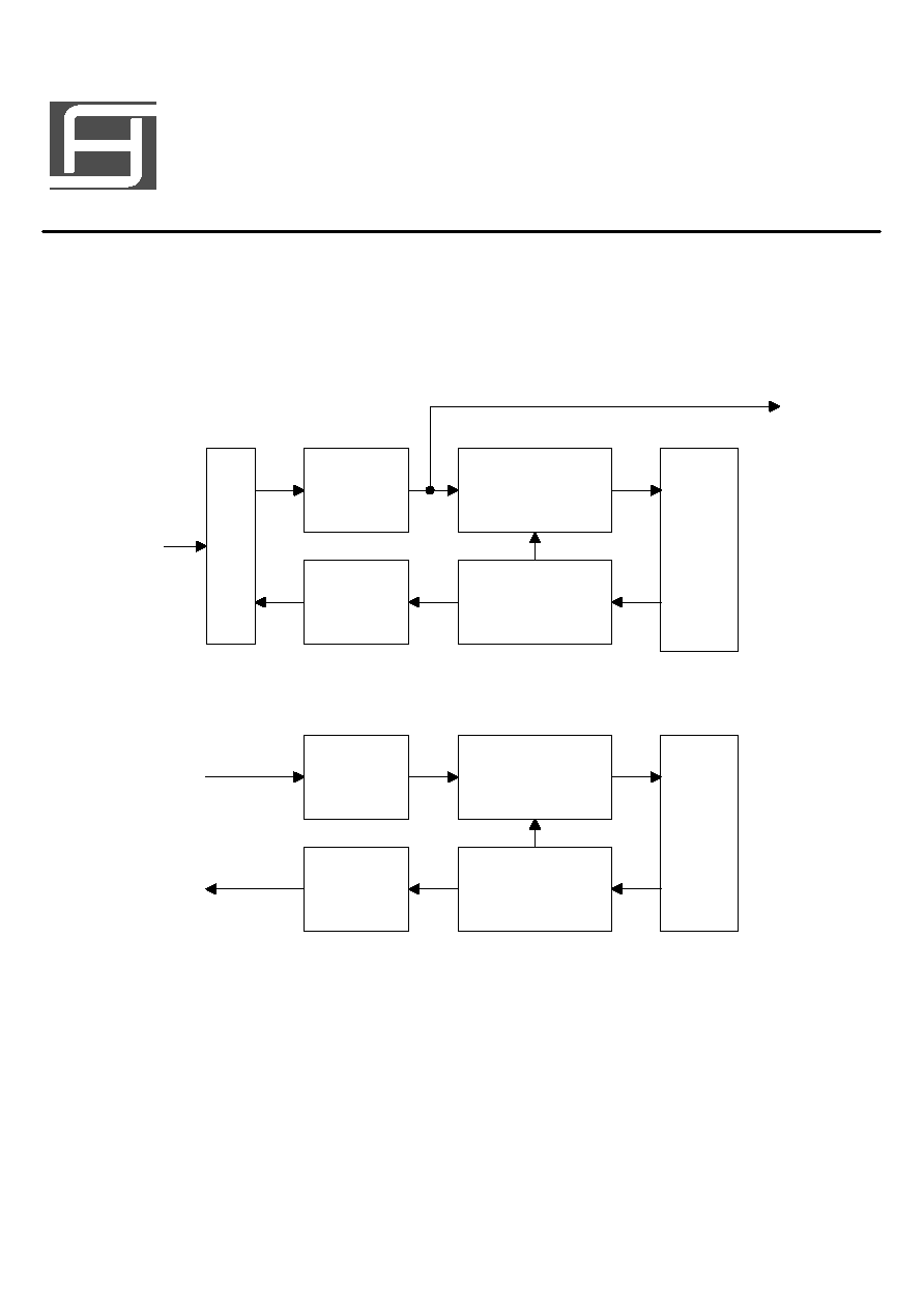
DESCRIPTIONS:
SM7186
is an Audio Echo Processor
using CMOS Technology. It has built-in
AD/DA and 48KBits SRAM for time delay.
External Resister adjust large range
oscillation frequency and control delay
time. Many combination to fit your
applications.
FEATURE:
* Built-in adjustable OSC.
* Built-in power on reset circuit.
* Built-in 48KBits SRAM for delay control.
* Adjustable delay time setting:
30ms ~ 700ms
* Low operating current.
APPLICATIONS:
* VCD
* Karaoke
* TV
* Audio System
* Car Stereo
* VCR
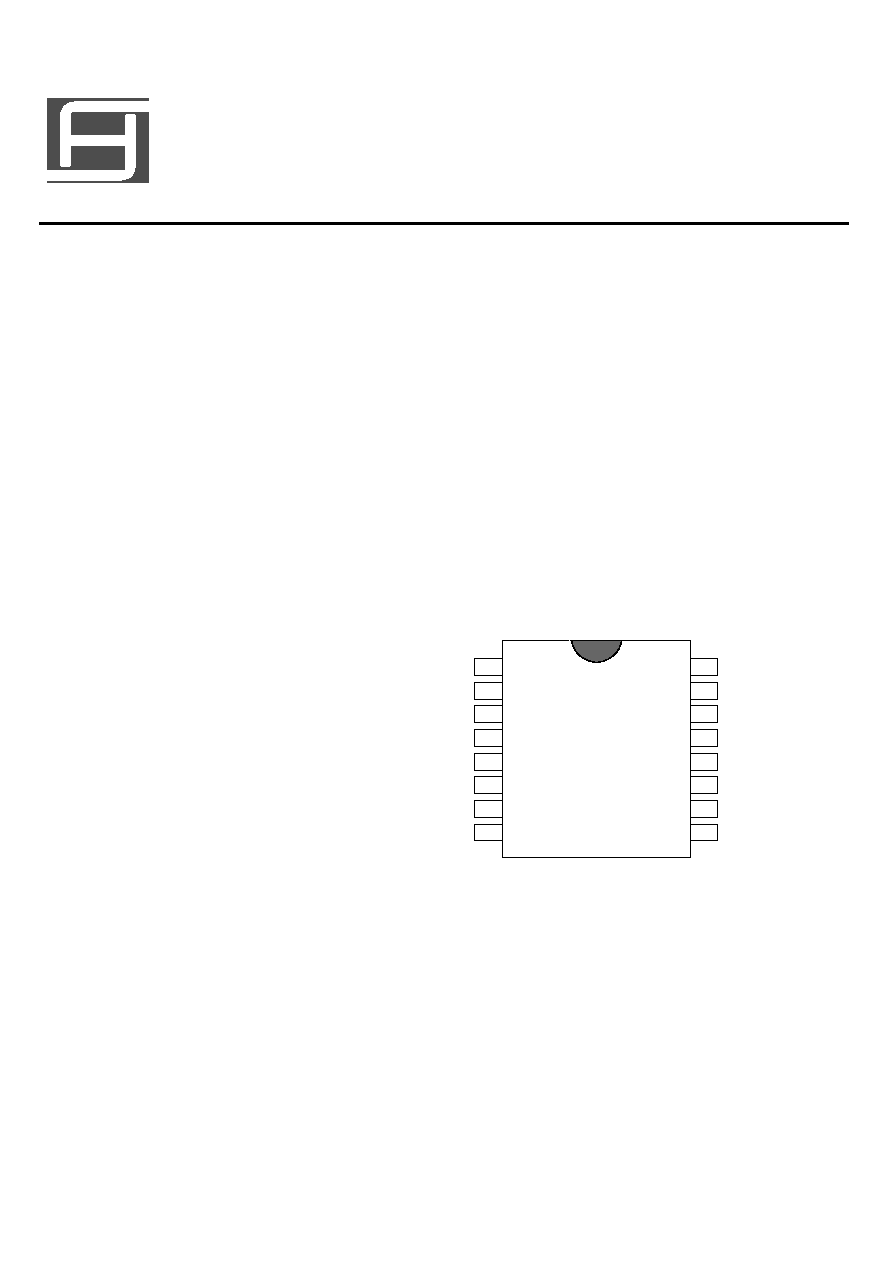
1
16
2
15
3
14
4
13
5
12
6
11
7
10
8
9
VDD
VREF
AGND
DGND
OSCO
OSCR
DACTL
ADCTL
OP1-IN
OP1-OUT
OP2-OUT
OP2-IN
DAC-OUT
DAC-IN
ADC-IN
ADC-OUT
�

Page 2
PIN No.
1
2
3
4
5
6
7
8
9
10
11
12
13
14
PIN DESCRIPTION
15
16
PIN NAME
VDD
VREF
AGND
DGND
OSCO
OSCR
DACTL
ADCTL
ADC-OUT
ADC-IN
DAC-IN
DAC-OUT
OP2-IN
OP2-OUT
OP1-OUT
OP1-IN
I/O
Power
AI/O
Power
Power
OSC
OSC
AIN
AIN
AOUT
AIN
AIN
AOUT
AIN
AOUT
AOUT
AIN
FUNCTION
Positive power supply
Analog reference voltage
Analog negative power supply
Digital negative power supply
System clock output
Add resistor to modify internal OSC
DAC control
ADC control
ADC OP output
ADC OP input
DAC OP input
DAC OP output
OP2 input
OP2 output
OP1 output
OP1 input
�

ECHO MODE APPLICATION CIRCUIT(MODIFIED)
1
16
2
15
3
14
4
13
5
12
6
11
7
10
8
9
Page 9
0.1 F
47 F
+5V
�
�
R
0.1 F
0.1 F
�
�
560pF
10K
OUTPUT
10 F
�
5.6K
�
560pF
10K
100K
INPUT
3900pF
15K
4.7 F
10K
15K
3300pF
OSCR
50K
4.7K
10 F
�
�
4.7 F
NOV. 2000
1. Pin 6 R is approximate 1K~160k .
2. Represent Analog Ground.
3. Represent Digital Ground.
SM7186
100 F
�
�
0.082 F
0.01 F
�
10K
10K
�
0.082 F
�
V.1.0, 2000