 | –≠–ª–µ–∫—Ç—Ä–æ–Ω–Ω—ã–π –∫–æ–º–ø–æ–Ω–µ–Ω—Ç: bw2010p | –°–∫–∞—á–∞—Ç—å:  PDF PDF  ZIP ZIP |

The BW2010P is a Phase-Locked Loop (PLL) frequency
synthesizer constructed in CMOS process technology.
The PLL macrofunctions provide frequency multiplication
capabilities.The output clock frequency, Fout, is related to the
reference input clock frequency, Fin, by the following equation:
Fout = ( m*Fin ) / ( p*s )
where Fout is the output clock frequency.
Fin is the reference input clock frequency. m,p and s are the
values for programmable dividers. BW2010P consists of a
Phase/Frequency Detector(PFD), a Charge Pump an External
Loop Filter, a Voltage Controlled Oscillator(VCO), a 6bit
Pre-divider, an 8bit Main divider and 2bit Post Scaler as shown
in Figure 1.
- 0.35um CMOS process technology
- 3.3 Volt Single power supply
- Output frequency range: 25~ 250 MHz
- Jitter: ±100ps
- Output Duty ratio: 40% to 60%
- Input Duty ratio: 40% to 60%
- Frequency changed by programmable divider
- Power down mode
General Description
Features
FUNCTIONAL BLOCK DIAGRAM
Pre Divider
P
Charge
Pump
PFD
VCO
Main Divider
M
Post Scaler
S
Loop Filter
(External)
FIN
Fout
25MHz ~ 250MHz FSPLL
BW2010P
SAMSUNG ELECTRONICS Co. LTD
Figure 1. FUNCTIONAL BLOCK DIAGRAM
FEB. 2000. Ver1.2.21

25MHZ~250MHZ FSPLL
BW2010P
SEC ASIC
ANALOG
/11
NAME
I/O
TYPE
I/O PAD
PIN DESCRIPTION
VDDD
DP
vddd
Digital power supply
VSSD
DG
vssd
Digital ground
VDDA
AP
vdda
Analog power supply
VSSA
AG
vssa
Analog ground
VBBA
AG
vbba
Substrate ground
FIN
AI
pia_bb
External F
REF
input
FILTER
AO
poar50_bb
Pump out is connected to Filter
-A capacitor is connected between
the pin and analog ground
FOUT
DO
pot12_bb
25MHz~250MHz clock output
PWRDN
DI
picc_bb
FSPLL clock power down.
-If PWRDN is High, PLL does not operate
under this condition.
-If not used, tie it to VSSA.
P[5:0]
DI
picc_bb
The values for 6bit programmable pre-divider.
M[7:0]
DI
picc_bb
The values for 8bit programmable main
divider.
S[1:0]
DI
picc_bb
The values for 2bit programmable post scaler.
CORE PIN DESCRIPTION
I/O TYPE ABBR.
- AI : Analog Input
- DI : Digital Input
- AO : Analog Output
- DO : Analog Output
- AP : Analog Power
- AG : Analog Ground
- AB : Analog Sub Bias
- DP : Digital Power
- DG : Digital Ground
- DB : Digital Sub Vias
- BD : Bidirectional Port
CORE CONFIGURATION
FIN
PWRDN
M[0]
M[1]
M[2]
M[3]
M[4]
M[5]
M[6]
M[7]
P[0]
P[1]
P[2]
P[3]
P[4]
P[5]
S[0]
S[1]
FOUT
FILTER
bw2010p
2
VSSD
VSSA
VBBA
VDDD
VDDA
25MHZ~250MHZ FSPLL
BW2010P
SEC ASIC
ANALOG
/11
ABSOLUTE MAXIMUM RATINGS
(Ta=25∫C)
Characteristics
Symbol
Value
Unit
Applicable pin
DC Supply Voltage
V
DD
V
DDA
-0.3 to 3.8
V
VDDD,VDDA,VSSD,VSSA,
VBBA
DC Input Voltage
V
IN
-0.3 to V
DD
+0.3
V
P[5:0],M[7:0],
S[1:0],PWRDN
Storage Temperature
T
STG
-40 to 125
∫C
-
NOTES
1. ABSOLUTE MAXIMUM RATING specifies the values beyond which the device may be damaged
permanently. Exposure to ABSOLUTE MAXIMUM RATING conditions for extended periods may affect
reliability. Each condition value is applied with the other values kept within the following operating
conditions and function operation under any of these conditions is not implied.
2. All voltages are measured with respect to VSSD unless otherwise specified.
3. 100pF capacitor is discharged through a 1.5Kohm resistor (Human body model)
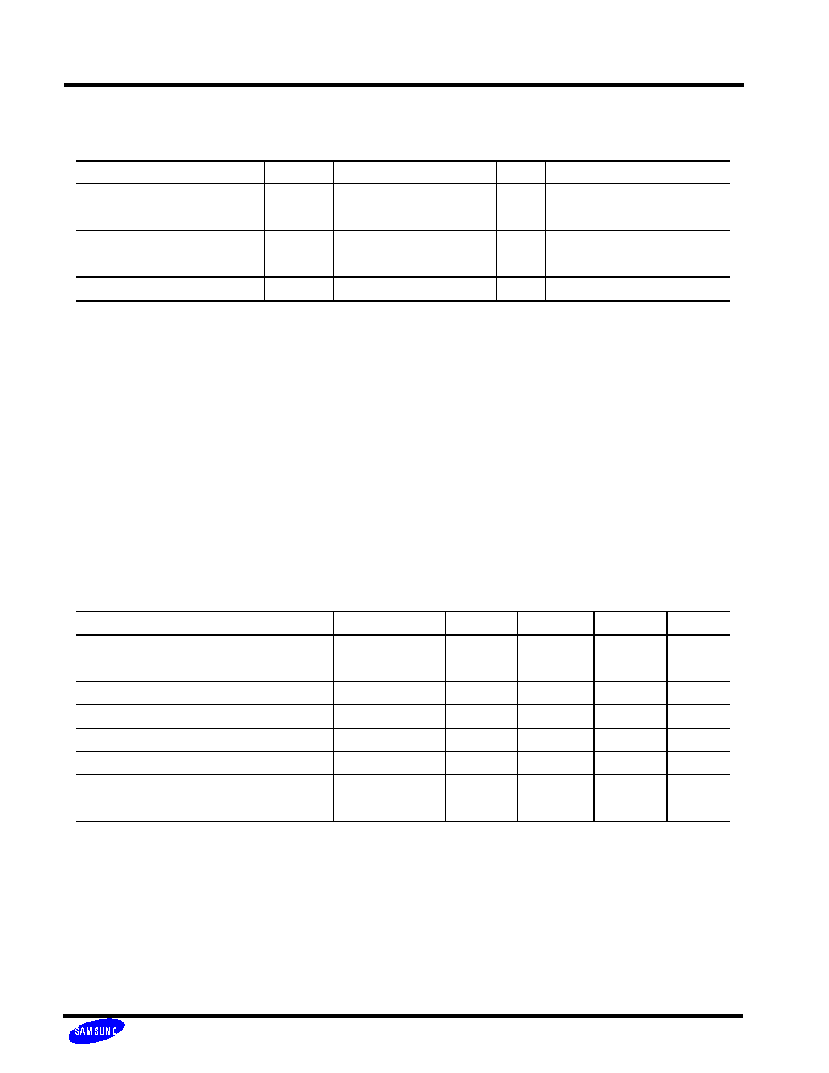
Recommended Operating Conditions
Characteristics
Symbol
Min
Typ
Max
Unit
Supply Voltage
V
DD
V
DDA
3.14
3.3
3.46
V
Supply Voltage Difference
V
DD
-V
DDA
-0.1
0.1
V
Oscillator(=Input) Frequency
Fosc
14.318
MHz
External Loop Filter Capacitor 1
C
LF1
390
pF
External Loop Filter Capacitor 2
C
LF2
30
pF
External Loop Filter Resistor
R
LF
9
Kohm
Operating Temperature
T
OPR
0
70
∫C
NOTES
1. It is strongly recommended that all the supply pins (VDDA, VDDD) be powered from the same source
to avoid power latch-up.
3

25MHZ~250MHZ FSPLL
BW2010P
SEC ASIC
ANALOG
/11
AC ELECTRICAL CHARACTERISTICS
Characteristics
Symbol
Min
Typ
Max
Unit
Input Frequency
F
IN
1
40
MHz
Output Clock Frequency
F
OUT
25
250
MHz
Output Clock Duty Cycle
T
OD
40
50
60
%
Input Clock Duty Cycle
T
ID
40
60
%
Lock-in Time
T
LT
100
us
Cycle to Cycle Jitter
T
JCC
-100
+100
ps
DC ELECTRICAL CHARACTERISTICS
Characteristics
Symbol
Min
Typ
Max
Unit
Operating Voltage
V
DD
/V
DDA
3.14
3.3
3.46
V
Digital Input Voltage High
V
IH
2.0
V
Digital Input Voltage Low
V
IL
0.8
V
Dynamic Current @250MHz
Idd
5
mA
Power Down Current
Ipd
100
uA
4

25MHZ~250MHZ FSPLL
BW2010P
SEC ASIC
ANALOG
/11
Functional Description
A PLL is the circuit synchronizing an output signal (generated by a VCO) with a reference
or input signal in frequency as well as in phase.
In this application, it includes the following basic blocks.
. The voltage-controlled oscillator to generate the output frequency.
. The divider P to divide the reference frequency by p.
. The divider M to divide the VCO output frequency by m.
. The divider S to divide the VCO output frequency by s.
. The phase frequency detector to detect the phase difference between the reference frequency
and the output frequency (after division) and to control the charge pump voltage.
. The loop filter to filter out high frequency components in charge pump voltage and give
smooth and clean control to VCO.
The m, p, s values can be programmed by 16bit digital data from the external source. So the PLL
can be locked onto the desired frequency.
Fout = ( m*Fin ) / ( p*s )
Fin = 14.318MHz, m=M+8 , p=P+2, s=2^S
Digital data format:
NOTES
. S[1] - S[0] : Output Frequency Scaler
. M[7] - M[0] : VCO Frequency Divider
. P[5] - P[0] : Reference Frequency Input Divider
. Every M,P and S values is not available. so your M,P,S values should be checked by bw2010p designer.
bw2010p designer can recommand suitable values.
Main Divider
Pre Divider
Post Scaler
M[7],M[6],M[5],M[4],M[3],M[2],M[1],M[0]
P[5],P[4],P[3],P[2],P[1],P[0]
S[0],S[1]
5
25MHZ~250MHZ FSPLL
BW2010P
SEC ASIC
ANALOG
/11
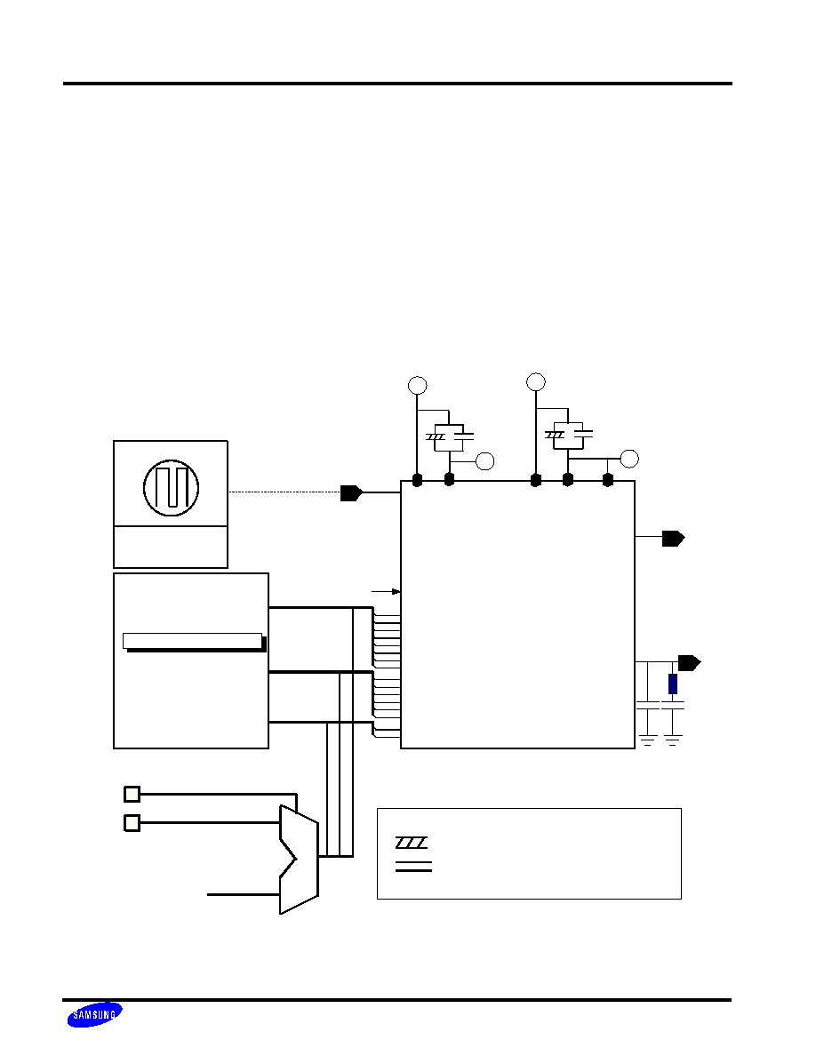
CORE EVALUATION GUIDE
For the embedded PLL, we must consider the test circuits for the embedded PLL core in
multiple applications. Hence, the following requirements should be satisfied.
- The FILTER and FOUT pins must be provided for test.
- For PLL test (Below 2 examples),
it is needed to control the dividers - M[7:0],P[5:0] and S[1:0] -that generate multiple clocks.
#1. Registers can be used for easy control of divider values.
#2. N sample bits of 16-bit divider pins can be bypassed for test using MUX.
NOTES
: 10uF ELECTROLYTIC CAPACITOR
UNLESS OTHERWISE SPECIFIED
: 103 CERAMIC CAPACITOR
UNLESS OTHERWISE SPECIFIED
FOUT
FILTER
bw2010p
#1.16bit Register Block
PWRDN
P[5:0]
S[1:0]
390pF
M[7:0]
FIN
External
Clock
Source
If Crystal isn't used,
the XTALIN is FIN
VDDD VSSD
VDDA VSSA
3.3V Digital Power
3.3V Analog Power
GND
GND
VSSA
Select Pin
Test Pins of N Sample bits
Internal Divider Signal Line
#2
M
U
X
VBBA
30pF
9Kohm
6

25MHZ~250MHZ FSPLL
BW2010P
SEC ASIC
ANALOG
/11
- The digital power(VDDD,VSSD), the analog power(VDDA,VSSA) and the bulk power(VBBA) must be
dedicated to the PLL seperately. If the dedicated VDDD and VSSD are not allowed, the pins of the
mallest power consuming block are shared with the PLL.
- The POA_BB pad is used as a FILTER pad that contains only ESD production diodes without any
resistors and buffers.
- The FOUT and FILTER pins must be placed away from the internal signals in order to avoid
overlapping signal lines.
- The blocks having a large digital switching current must be located away from the PLL core.
- The PLL core must be shielded by guardring.
- For the FOUT pad, you can use a custom drive buffer or POT12_BB buffer considering the drive
current.
CORE LAYOUT GUIDE
7

25MHZ~250MHZ FSPLL
BW2010P
SEC ASIC
ANALOG
/11
PACKAGE CONFIGURATION
NOTES
1.CP40,CP80,PTSEL pins are internal dummy block test pins.
So CP40 and CP80 are tied to VDDA or VSSA, and PTSEL pin is tied to VDDP or VSSP.
2
1
4
3
6
5
8
7
9
12
11
35
36
33
34
31
32
29
30
27
28
25
26
13
14
16
17
18
19
20
21
23
24
48
47
46
45
44
43
42
41
40
39
38
37
22
P
T
S
E
L
A
L
A
L
A
D
V
D
D
P
P
N
C
CP40
XTALIN
XTALOUT
NC
N
C
P
[5]
P
[4]
P
[3]
P
[2]
P
[1]
P
[0]
R
E
S
E
T
V
S
S
D
M[7]
M[6]
M[5]
M[4]
M[3]
M[2]
M[1]
M[0]
S[1]
S[0]
BW2010P
C
10uF
103
C
L
H
L
H
L
H
L
H
L
H
L
H
L
H
L
H
L
H
L
H
L
H
L
H
L
H
L
H
L
H
L
H
3.3V Analog Power
14.318MHz
2bit Post Scaler
8bit Main Divider
3.3V PAD Power
F
O
U
T
L
H
V
S
S
P
P
390pF
9Kohm
30pF
F
I
L
T
E
R
N
C
V
S
S
A
P
V
D
D
A
P
C
10
V
B
B
A
P
L
H
CP80
L
H
15
ID16
ID18
NC
NC
NC
NC
NC
NC
N
C
N
C
N
C
L
H
L
H
PWRDN
6bit Pre Divider
VDDD
C
3.3V Digital Power
N
C
8

25MHZ~250MHZ FSPLL
BW2010P
SEC ASIC
ANALOG
/11
NAME
PIN NO
I/O TYPE
PIN DESCRIPTION
VDDD
37
DP
Digital power supply
VSSD
36
DG
Digital ground
PWRDN
48
DI
FSPLL clock power down
-If PWRDN is High, PLL does not operate under
this condition.
- If not used, tie it to VSSD.
RESET
35
DI
PLL M,P divider block resigistor setting reset
P[0]~P[5]
27~32
DI
Pre-Divider Input(LSB)
VDDA
10
AP
Analog power supply
VSSA
8
AG
Analog ground
VBBA
11
AG
Substrate ground
XTALIN/FIN
13
AI
Crystal input or external F
REF
input
XTALOUT
12
AO
Crystal output
-If a crystal is used, it is connected to
the I/O pins, XTALIN and XTALOUT.
If not used, they are floating.
VSSP
4
PG
PAD ground
VDDP
3
PP
PAD supply power
FOUT
1
DO
25MHZ~250MHz clock output
FILTER
6
AO
Pump out is connected to the FILTER.
PTSEL
2
DI
Internal test block(MUX) input Do not float this pin. It
must be tied to VDDP or VSSP
CP40
14
AI
Charge pump current switch(20uA)
CP80
15
AI
Charge pump current switch(40uA)
VSSA
8
AG
Analog ground
M[0]~M[7]
38~45
DI
8bit main divider input
S[0]~S[1]
46~47
DI
2bit post divider input
ID16
16
AO
Identification resistor output
ID18
18
AO
Identification resistor output
NOTES
1. I/O TYPE PP and PG denote PAD power and PAD ground respectively.
PACKAGE PIN DESCRIPTION
9

25MHZ~250MHZ FSPLL
BW2010P
SEC ASIC
ANALOG
/11
PLL Introduction
De-Skew Function
In semiconductor manufacturing, smaller device geometry facilitate greater on-chip density and higher chip
performance. System performance is compromised, however, by clock skew which occures when the clock
on a chip is not synchronized to the system clock. The degree of clock skew varies from chip to chip
because of variations in process, temprature, power supply, interconnects, and routing. The PLL trackes
the system clock and compares it with the on-chip clock, then adjusts the latter until it matches the former
in frequency and phase.
Frequency Synthesis Function
Frequency synthesis uses the system clock as a base frequency to generate higher/lower frequency clocks
for internal logic. For high speed applications in high-end designs, transmission line effects cause problems
because of parastics and impedance mismatch among various on-board components. These problems can be
eliminated by moving the high frequency to the chip level. On-chip clocks that are faster than the external
system clock can be synthesized by inserting a divider in the feedback path. The divider is placed after voltage
controlled oscillator, as illustrated in Figure1. The signal is running at M times the system clock frequency, so
the PLL matches the divider signal output to the system clock. This configuation reduces the problem of
interfacing to the system clock on the board, and it reduces the noise generated by the system clock oscillator
and driver for all the components in the system
PLL Components
Figure6 is block diagram of the components of a PLL: phase frequency detector, charge pump, voltage controlled
oscillator, and loop filter. In SEC technology, the loop filter is implemented as external components close to chip.
Phase detector : The phase dectector monitors the phase difference between the Fin and Fout, and generates a
control signal when it detects difference between the two. If the Fin frequency is higher than the Fout frequency,
its falling edge occures before(lead) the falling edge of the Fout output. When this occures the phase detector
signals the VCO to increase the frequency of the on-chip clock. If the falling edge of the Fin occures after(lag)
the falling edge of the Fout output, the detector signals the VCO to decrease on-chip clock frequency. If the
frequencies of the Fin and Fout are the same, the detector does not generate a control signal, so the
frequencies remain the same.
Charge Pump : The charge pump converts the phase detector control signal to a charge in voltage across the
external filter that drives the VCO. As the Voltage Controlled Oscillator decreases, or increases, If the voltage
remains constant, the frequency of the oscillator remains constant.
Loop Filter
: The control signal that the phase detector generates for the charge pump may generate large
excursions (ripples) each time the VCO output is compared to the system clock. To avoid overloading the VCO,
a low pass filter samples and filters the high-frequency components out of the control signal. the filter is typically
a single-pole RC filter consisting of a resistor and capacitor.
Voltage Controlled Oscillator(VCO) : The output voltage from the loop filter drives the VCO, causing its
oscillation frequency to increas or decrease as a function of variations in voltage. When the VCO output
matches the system clock in frequency and phase, the pahse detector stops sending a control signal to the
charge pump, which in turn stabilizes the input voltage to the loop filter. The frequency then remains constant,
and the PLL remains locked onto the system clock.
10

25MHZ~250MHZ FSPLL
BW2010P
SEC ASIC
ANALOG
/11
Design Considerations
The following design consideratios apply:
* Phase tolerance and jitter are independent of the PLL frequency.
* Jitter is affected by the noise frequency in the power(VDDD/VSSD,VDDA/VSSA and VBBA). It increases
when the noise level increases.
* A CMOS-level input reference clock is recommend for signal compatibility with the PLL circuit. Other
levels such as TTL may degrade the tolerances.
* The use of two, or more PLLs requires special design considerations. Please contact SEC's application
engineer for more information.
* The following apply to the noise level, which can be minimized by using good analog power and
ground isolation techniques in the system:
- Use wide PCB traces for POWER(VDDD/VSSD, VDDA/VSSA and VBBA) connections to the PLL core
Seperate the traces from the chip's VDDD/VSSD,VDDA/VSSA and VBBA supplies.
- Use proper VDDD/VSSD,VDDA/VSSA and VBBA de-coupling.
- Use good power and ground sources on the board.
* The PLL core should be placed as close as possible to the dedicated loop filter and analog Power
and ground pins.
* It is inadvisable to locate noise-generating signals, such as data buses and high-current outputs, near
the PLL I/O cells.
* Other related I/O signals should be placed near the PLL I/O but do not have any pre-defined
placement restriction
Fin
Charge
Pump
PFD
VCO
Loop Filter
(External)
Fout
Figure 6. Main Components of PLL
11