Document Outline
- The S1A0429A is a monolithic integrated circuit designed for filterless and coilless FM IF detect...
- It includes the external 2nd IF ceramic filter and the external discriminator in itself and that ...
- (Vcc = 3V, fc = 98MHz, fDEV = ± 22.5kHz, fMOD = 1kHz, Ta = 25∞C, VRFin = 150mVrms, unless otherwi...
- C1 Eliminates IF harmonics at the output of the demodulator.
- C2 Stabilizes on/off switching of audio signal path. The function of path control block can contr...
- C5, L5, Cv Determines the frequency of the local oscillator. Oscillated level can be suppressed w...
- C6 Decouples the DC feedback of limiter.
- C7, C8, C10 Determine the center frequency and bandwidth of active IF bandpass filter. This BPF d...
- Internal parts
- Ri10 = 2.2kW, Ci10 = 148pF
- Ri7 = 4.7kW
- Ri8 = 4.7kW
- C9 Eliminates IF harmonics at the RSSI output.
- R9 Determines RSSI slope which is inversely proportional to RFin(dBm), adjust the slope and level...
- C15, C16 Determines the cut-off frequency of audio band pass filter C15 determines the high cut-o...
- Internal parts
- Ri15 = 12.3kW
- Ri16 = 14kW

FILTERLESS WIDEBAND FM IF DETECTOR
S1A0429A
1
INTRODUCTION
The S1A0429A is a monolithic integrated circuit designed for filterless
and coilless FM IF detector used in the cordless telephone.
It includes the external 2nd IF ceramic filter and the external
discriminator in itself and that realized to be able to reduce the
external parts extremely.
FEATURES
∑
Operating voltage range: 2.0 to 6.0V
∑
Typical supply current: 6.3mA at 3V
∑
Filterless & coilless FM IF detector
-- Excellent demodulation characteristics
-- Intermediate frequency is 76kHz
-- Include the IF band pass filter (active RC filter)
-- Include the phase shifter (for discriminator)
-- Dual feedback IF detect system (for the image rejection of mixer)
-- The only function to be tuned is the resonant frequency of the oscillator
-- Minimum number of external parts required
ORDERING INFORMATION
Device
Package
Operating Temperature
S1A0429A01-S0BA
16
-
SOP
-
225
-
10
∞
C to +70
∞
C
16
-
SOP
-
225

S1A0429A
FILTERLESS WIDEBAND FM IF DETECTOR
2
BLOCK DIAGRAM
PIN CONFIGURATION
1
2
3
4
5
6
7
8
16
15
14
13
12
11
10
9
Demodulator
Path control
Audio Filter
DEM
O
TMC
GND
Vcc
OSC
DECPL
IFLT4
IFLT3
RSSI
IFLT2
IFLT1
RFin+
RFin-
AF
O
AFLT2
AFLT1
Mixer
BPF
Limiter
vco
1
2
3
4
5
6
7
8
16
15
14
13
12
11
10
9
S1A0429A
DEMo
TMC
GND
Vcc
OSC
DECPL
IFLT4
IFLT3
AFLT1
AFLT2
AFo
RFin-
RFin+
IFLT1
IFLT2
RSSI

FILTERLESS WIDEBAND FM IF DETECTOR
S1A0429A
3
PIN DESCRIPTION
ABSOLUTE MAXIMUM RATINGS
Pin No.
Symbol
Description
1
DEM
O
Demodulator output terminal, low pass filtering with the external capacitor
2
TMC
This terminal stabilizes the control of audio signal path with the external capacitor
3
GND
Ground
4
Vcc
Supply voltage
5
OSC
Local oscillator terminal
The external local signal injection is possible as this terminal connects resister to Vcc
6
DECPL
Internal IF AMP (Limiter) de-coupling terminal for DC bias
7
IFLT4
IF band pass filter terminal for high cut-off frequency
8
IFLT3
IF band pass filter terminal for low cut-off frequency
9
RSSI
Received signal strength indicator
10
IFLT2
If band pass filter terminal for high cut-off frequency
11
IFLT1
If band pass filter terminal for low cut-off frequency
12
RFin+
Balanced input terminal of mixer
13
RFin-
Balanced input terminal of mixer
14
AF
O
Recovered audio output terminal
15
AFLT2
Audio signal band pass filter terminal for high cut-off frequency
16
AFLT1
Audio signal band pass filter terminal for low cut-off frequency
Characteristics
Symbol
Value
Unit
Maximum supply voltage
Vcc
7
V
Operating temperature
T
OPR
-
10 to +70
∞
C
Storage temperature
T
STG
-
55 to +150
∞
C
S1A0429A
FILTERLESS WIDEBAND FM IF DETECTOR
4
ELECTRICAL CHARACTERISTICS
(Vcc = 3V, fc = 98MHz, f
DEV
=
±
22.5kHz, f
MOD
= 1kHz, Ta = 25
∞
C, VRFin = 150
µ
Vrms, unless otherwise specified)
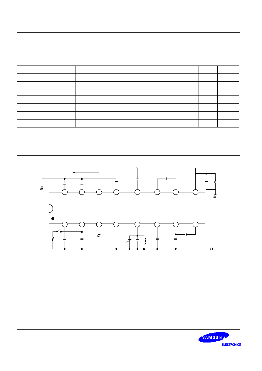
TEST CIRCUIT
Characteristics
Symbol
Test conditions
Min.
Typ.
Max.
Unit
Current consumption
Icc
-
-
6.3
8.0
mA
Input for -3dB limiting
V
LIM
AFo = -3dB
0dB Ref = 150
µ
Vrms RFin
-
5.0
13
µ
Vrms
S/N ratio
S/N
-
45
60
-
dB
Detector output distortion
THD
DET
-
-
0.7
-
%
Recovered audio output
V
O(RA)
-
-
90
-
mVrms
AM rejection ratio
AMRR
AM modulation = 30%
40
50
-
dB
1
2
3
4
5
6
7
8
16
15
14
13
12
11
10
9
S1A0429A
R2
10k
C1
10n
C2
100n
GND
Cv
2-6p
C5
56p
L5
2.7
µ
F
C6
100n
C7
1.5n
C8
820p
Vcc
R9
8.2K
C9
100n
RSSI
C10
4.7n
C12
220p
RFin (98MHz)
C13
220p
C15
3.3n
C16
100n
GND
AF OUTPUT

FILTERLESS WIDEBAND FM IF DETECTOR
S1A0429A
5
APPLICATION CIRCUIT
1
2
3
4
5
6
7
8
16
15
14
13
12
11
10
9
S1A0429A
10k
6.8n
10n
GND
56p
Vcc
100n
1.5n
560p
Vcc
100K
0.1
µ
RSSI
4.7n
560p
RFin (10.7MHz)
220p
3.3n
0.1u
GND
AF OUTPUT
shin Woo
'
s coil
7BS-C4037
TEL: 832-0343-74-5040
330

S1A0429A
FILTERLESS WIDEBAND FM IF DETECTOR
6
EXTERNAL PARTS DESCRIPTION (See Figure 3)
C1
Eliminates IF harmonics at the output of the demodulator.
C2
Stabilizes on/off switching of audio signal path.
The function of path control block can controlled by audio on/off signal path from demodulator to
audio filter
If R2 is connected to PIN2, audio signal path is always on state.
C5, L5, Cv
Determines the frequency of the local oscillator. Oscillated level can be suppressed with shunt
resistor.
The values of C5, L5 and Cv depend on the required tunning range.
Decouples the DC feedback of limiter.
C6
Decouples the DC feedback of limiter.
C7, C8, C10 Determine the center frequency and bandwidth of active IF bandpass filter.
This BPF determines selectivity characteristics and demodulated output distortion characteristics.
C7, C10 determines the high cut-off frequency (f
HP
).
C8 determines the low cut-off frequency (f
LP
).
C9
Eliminates IF harmonics at the RSSI output.
R9
Determines RSSI slope which is inversely proportional to RFin(dBm), adjust the slope and level of
RSSI output.
C15, C16
Determines the cut-off frequency of audio band pass filter
C15 determines the high cut-off frequency (f
HP
).
C16 determines the low cut-off frequency (f
LP
).
f
LP1
1
C
i10
C
10
2
R
i10
---------------------------------------
=
f
HP2
1
2
R
i7
C
7
-----------------------
=
f
LP2
1
2
R
i8
C
8
-----------------------
=
Internal parts
R
i10
= 2.2k
, C
i10
= 148pF
R
i7
= 4.7k
R
i8
= 4.7k
f
HP
1
2
R
i15
C
15
-----------------------------
=
f
LP
1
2
R
i16
C
16
-----------------------------
=
Internal parts
R
i15
= 12.3k
R
i16
= 14k