DUAL EQ AMP WITH ALC
S1A2224A01
1
INTRODUCTION
The S1A2224A01 is a monolithic integrated circuit consisting of
a dual equalizer amplifier with ALC, and it is suitable for stereo
radio cassette-tape players.
FEATURES
∑
Dual equalizer amplifier with a built-in ALC circuit
∑
Recording amp available because of high gain characteristics
(Variable monitor possible)
∑
Good channel separation (sep = 50dB Typ)
∑
Quick stabilization after power on
∑
Capable of direct meter driving and ALC transistor
∑
Good ALC response balance between channels
∑
Wide operating supply voltage range: Vcc = 4V -- 13V
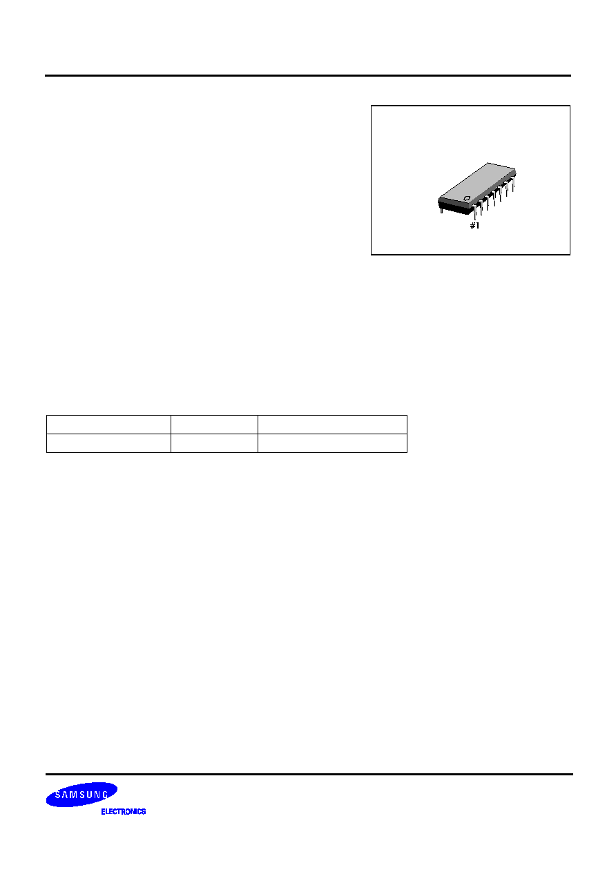
ORDERING INFORMATION
Device
Package
Operating Temperature
S1A2224A01-D0B0
14
-
DIP
-
300
-
20
∞
C -- +70
∞
C
14
-
DIP
-
300

DUAL EQ AMP WITH ALC
S1A2224A01
3
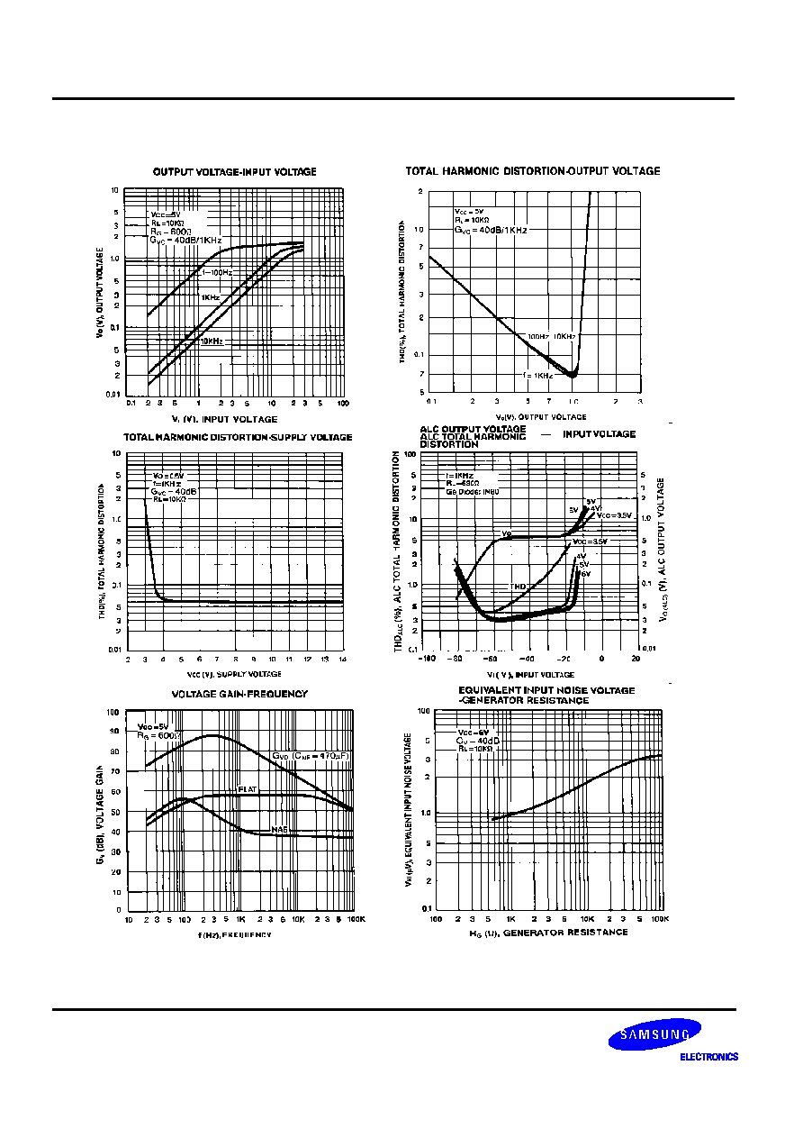
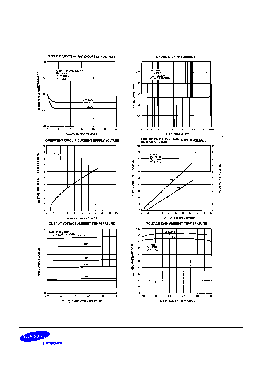
ELECTRICAL CHARACTERISTICS
(Ta = 25
∞
C, Vcc = 5V, R
L
= 10k
, f = 1kHz: play, R
L
= 680
: Recording)
Characteristic
Symbol
Test Conditions
Min.
Typ.
Max.
Unit
Quiescent Circuit Current
I
CCQ
V
I
= 0
-
4.5
10
mA
Open Loop Voltage Gain
G
VO
-
-
85
-
dB
Closed Loop Voltage Gain
G
VC1
Play
-
40
-
dB
G
VC2
Record
-
58
-
dB
Output Voltage
V
O
THD =1%, Play
0.9
1.2
-
V
Total Harmonic Distortion
THD
V
O
= 0.5V, Play
-
0.1
1.0
%
Input Resistance
R
I
-
21
30
-
k
Equivalent Input Noise Voltage
V
NI
BW (
-
3dB)
= 20Hz
-
20kHz
-
1.0
2.0
µ
V
Cross Talk
CT
R
G
= 2.2k
40
50
-
dB
ALC Range
V
ALC
V
I
=
-
60dBm, Record
35
45
-
dB
ALC Balance
CB
ALC
V
I
=
-
20dBm, Record
-
0
2.0
dB
ALC Distortion
THD
ALC
V
I
=
-
20dBm, Record
-
0.5
2.0
%
DUAL EQ AMP WITH ALC
S1A2224A01
7
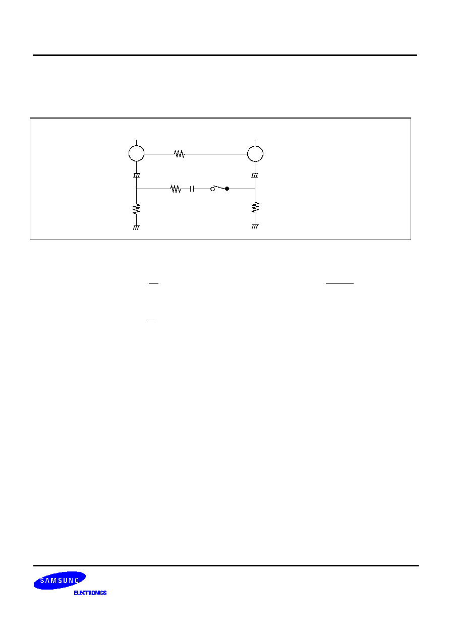
APPLICATION INFORMATION
Closed Loop Voltage Gain
SW on: play
SW off: record
4
2
+
+
10
µ
C
3
R
L
0.033
µ
C
2
R
2
4.7K
51K
Z
R
1
C1
R
F
56
22
µ
A. Playback amplifier
Gv = 20 log (dB) at f =1 kHz, G
V
= 42 dB (Typ) Z = R
1
//(R
2
+ )
B. Recording amplifier
Gv =20 log (dB) at f =1 kHz, G
V
= 58 dB (Typ)
Z
R
F
1
2
f
∑
C
2
R1
R
F
S1A2224A01
DUAL EQ AMP WITH ALC
8
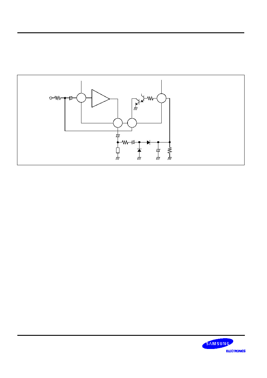
ALC Circuit
The ALC circuit consists of TR
1
, TR
2
and some external components. The output level of the amplifier is recti-fied
by external circuits. Since this DC level is applied to the ALC input terminal (Pin 7), the impedance between the col-
lector and emitter of TR1 can change its value. Therefore, the pre-amplifier input level can be controlled.
+
+
+
5
7
6
2
INPUT
+
C
1
INPUT
R
4
D
1
R
L
C
4
R
2
C
2
D
3
D
2
R
3
R
1
TR
2
TR
1