
69
GH-039
HYBRID GATE DRIVER IC FOR IGBT
I
FO
Fault output current
mA
10.0
17.0
SanRex Hybrid Gate Driver IC for IGBT
High Voltage isolation by Photo Coupler
Enable to drive IGBT up to dual 300A module
Operate with single power source
Support to high-density system design
Built-in Photo Coupler input resistor
330
Built-in over current protection circuit with soft shutdown
characteristic
Output terminals on over current detection
Maximum Ratings
Unless otherwise Tj
25
Equivalent Circuit
Symbol
Item
V
CC
Supply Voltage
Conditions
Ratings
Min.
Typ.
Max.
Unit
V
23.0
26.0
28.0
V
OH
Forward Bias Output Voltage
V
CC
26.0V
V
15.4
17.5
18.0
V
RB
Reverse Bias Supply Voltage
V
CC
26.0V
V
0
7.0
0
8.0
10.0
V
FIN
Photo Coupler Input Voltage
V
0
5.0
0
7.0
I
F
Photo Coupler Input Current
V
FIN
5.0V
mA
0
9.0
10.0
11.5
I
g
1
Output Forward Current
PW
2
s
Dutycycle
0.05
A
0
4.0
0
6.0
I
g
2
Output Reverse Current
PW
2
s
Dutycycle
0.05
A
0
4.0
0
6.0
t
PLH
Switching Time-High side
V
CC
26.0V
I
F
10mA
s
0
1.5
t
PHL
Switching Time-Low side
V
CC
26.0V
I
F
10mA
s
0
1.5
t
r
Rise Time
V
CC
26.0V
I
F
10mA
s
0
1.0
t
f
Fall Time
V
CC
26.0V
I
F
10mA
s
0
1.0
V
OC
Overcurrent trip level
V
CC
26.0V
V
11.5
12.0
12.5
t
OCP
OCP delay time
V
CC
26.0V
I
F
10mA
s
0
4.0
10.0
t
pcotf
OCP rise and fall time
V
CC
26.0V
I
F
10mA
s
0
2.0
0
5.0
t
ALM
Alarm output delay time
V
CC
26.0V
I
F
10mA
s
0
1.0
0
5.0
5k
10k
dv/dt
Common Mode Transient immunity
V/
s
Visc
Input
Output Isolation Voltage
AC50/60H
Z
1minute
V
Topr
Operational Ambient Temperature
Tstg
Storage Temperature
AC3750
25
80
40
125
The model name is indicated on the back of the product.
70
GH-039
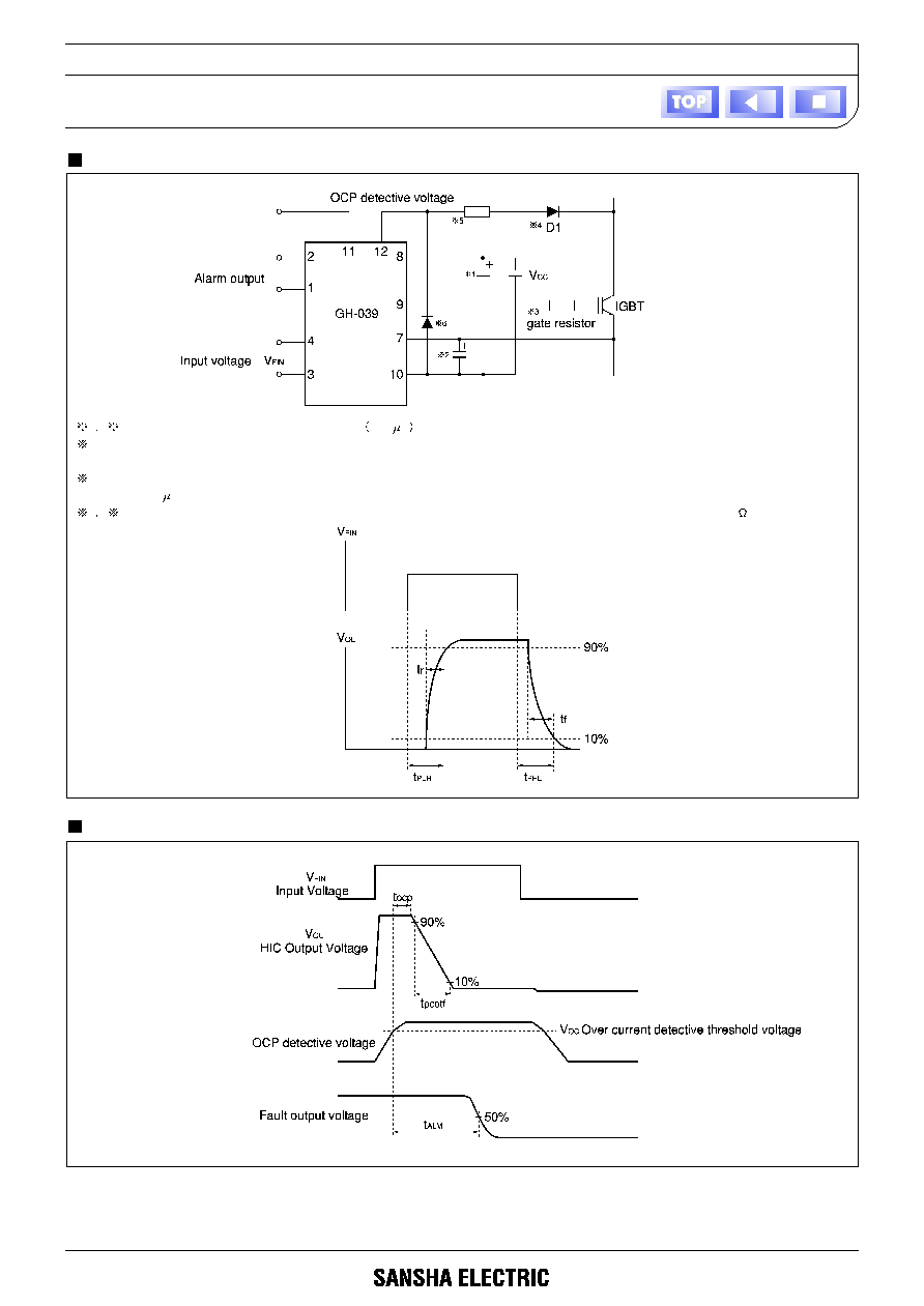
Example of Application
Definition of over current protection function
1
2
To assure required voltage the capacitor
>10
F
has to be connected as close to the Driver IC as possible.
3
For the value of gate resistor the resistance value described in IGBT Module specification is recommended. The gate resistance should
be determined at less than 6A of peak output current judging from signal delay time and surge voltage.
4
For D1 use a fast diode with same blocking voltage as IGBT. Required current capacity is 0.1 to 1.0A, reverse recovery time has to be
less than 0.4
s.
5
6
To prevent malfunction of detection for over current protection, apply resistor and diode with value around 100