SanRex 50 Seaview Blvd. Port Washington, NY 11050-4618 PH.(516)625-1313 FAX(516)625-8845 E-mail: semi@sanrex.com
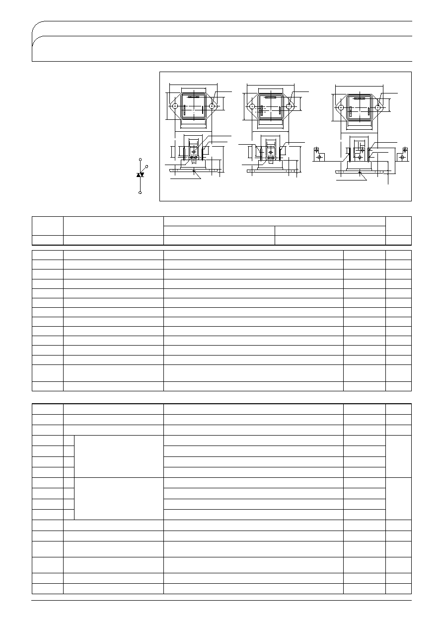
TG35C/E/D
TRIAC
ISOLATED TYPE
39.2 MAX
20.1 MAX
21.6 MAX
30.0±0.1
1.7T
1
.T
2
.G
1.7G
G
T
1
7.35
±
0
.2
1.65
4.6
±
0.2
22.0 MAX
8.2MAX
2.6
±
0.1
2.5T
1
.T
2
13.9±0.2
Tc Pointdepth 2mm
T'
T
T
2
T
1
G
2-4.2±0.1
23.0 MAX
10.8
±
0.2
T
1
T=6.35, T'=8.25, t=0.8
T
2
T=6.35, T'=8.25, t=0.8
G
T=4.75, T'=5.7, t=0.5
Maximum Ratings
Tj=25 unless otherwise specified
Symbol
Item
TG35C40
Ratings
TG35C60
Unit
V
DRM
Repetitive Peak Off-State Voltage
400
600
V
Symbol
Item
Conditions
Ratings
35
Unit
I
T
RMS
R.M.S. On-State Current
I
TSM
Surge On-State Current
Tc
58
One cycle, 50Hz/60Hz, peak, non-repetitive
I
2
t
I
2
t
P
GM
Peak Gate Power Dissipation
P
G
AV
Average Gate Power Dissipation
I
GM
Peak Gate Current
V
GM
Peak Gate Voltage
Value for one cycle of surge current
A
300/330
A
450
10
A
2
S
W
1
di/dt
Critical Rate of Rise of On-State Current
I
G
100mA
Tj
25
V
D
1
2
V
DRM
dI
G
/dt1A/s
Tj
Operating Junction Temperature
Tstg
Storage Temperature
V
ISO
Isolation Breakdown Voltage
R.M.S.
Mounting Torque
M4
Mass
A.C.1 minute
Recommended Value 1.0-1.4
10-14
Typical value
Excluding bolt, nut and wrapping material
3
W
A
10
V
50
A/
s
-25 to 125
-40 to 125
2500
1.5
15
23
V
N
m
kgfB
g
Symbol
Item
Conditions
Ratings
5
1.4
50
50
-
50
Unit
I
DRM
Reptitive Peak Off-State Current, max
V
TM
Peak On-State Voltage, max
V
D
=V
DRM
, Single phase, half wave, Tj
125
On-State Current
2◊I
T
RMS
Inst. measurement
I
GT1
1
2
3
4
Gate Trigger Current, max
I
-
GT1
I
GT3
I
-
GT3
V
GD
Non-Trigger Gate Voltage, min
dv/dt
Critical Rate of Rise on-State
Voltage,min.
Tj
25I
T
1AV
D
6V
Tj
25I
T
1AV
D
6V
mA
V
mA
Tj
25I
T
1AV
D
6V
3
3
-
3
0.2
20
5
30
1.5
V
GT1
1
2
3
4
Gate Trigger Voltage, max
V
-
GT1
V
GT3
V
-
GT3
Tj
25I
T
1AV
D
6V
Tj
25I
T
1AV
D
6V
V
Tj
25I
T
1AV
D
6V
Tj
125V
D
1
2
V
DRM
Tj
125V
D
2
3
V
DRM
Exoponential wave.
dv/dtc
Critical Rate of Rise off-State
Voltage at commutation, min
I
H
Holding Current, typ.
Rth
j-c Thermal Impedance, max
Tj
125V
D
2
3
V
DRM
di/dtc15A/ms
Tj
25
Junction to case
V
tgt
Turn On Time, max.
10
I
T
RMS
I
G
100mAV
D
1
2
V
DRM
Tj25dI
G
/dt1A/s
V
V/
s
V/
s
mA
/W
Electrical Characteristics
UL;E76102
M
T1
G
T2
Unit
A
TG35C/E/D are isolated molded triacs
suitable for wide range of applications like
copier, microwave oven, solid state switch,
motor control, light control and heater
control.
I
T
AV
35A
High surge capability 330A
Isolated Nounting
AC2500V
Tab Terminals
39.2 MAX
20.1 MAX
21.6 MAX
20.2 MAX
30.0±0.1
1.55G
+
-
0.2
0.0
2.0T
1
.T
2
+
-
0.2
0.0
7.95
±
0
.15
9.75
±
0
.3
6.35
±
0
.15
22.5 MAX
8.2
2.6
5-1.3±0.2
13.9
3.0±0.3
Tc Pointdepth 2mm
T
1
TAB250T=6.35, T'=8.25, t=0.8
T
2
TAB250T=6.35, T'=8.25, t=0.8
GTAB187T=4.75, T'=5.7, t=0.5
T'
T
T
2
T
1
G
2-4.2±0.1
23.0 MAX
10.8
39.2 MAX
20.1 MAX
21.6 MAX
20.2 MAX
30.0±0.1
1.3G
7.95
±
0.15
9.75
±
0
.3
6.35
±
0
.15
22.5 MAX
8.2
2.6
5-1.3±0.2
13.9
3.0±0.3
T'
T
T
2
T
1
G
2-4.2±0.1
23.0 MAX
10.8
2.0T
1
.T
2
+
-
0.2
0.0
T
1
TAB250T=6.35, T'=8.25, t=0.8
T
2
TAB250T=6.35, T'=8.25, t=0.8
GTAB187T=4.75, T'=5.7, t=0.8
7TG-C
7TG-E
7TG-D
SanRex 50 Seaview Blvd. Port Washington, NY 11050-4618 PH.(516)625-1313 FAX(516)625-8845 E-mail: semi@sanrex.com
TG35C/E/D
;
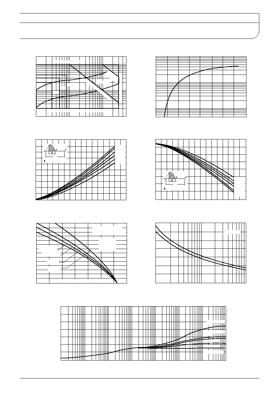
Gate Characteristics
Gate CurrentmA
-
Gate Voltage
V
Peak Gate Voltage10V
Peak Gate Current
3
A
Peak Gate
Power
10W
Gate
Distribution
Ave
ra
ge G
ate
P
ow
er1
W
-25
25
125
Maximum Gate Voltage that will not trigger any unit
On-State Voltage
On-State VoltageV
On-State Current
A
On State Current vs.
Maximum Power Dissipation
RMS On-State CurrentA
Power Dissipation
W
180
150
120
90
60
30
: Conduction Angle
360
2
On State Current vs.
Allowable Case Temperature
RMS On-State CurrentA
Allowable Case Temperature
30
60
90
120
150
180
: Conduction Angle
360
2
Ambient temp. vs. RMS On-State Current
Maximum Allowable Ambient Temperature
RMS On-State Current
A
Conduction Angle 180
Apply following figures for
different conduction angles
F-60 Rth1.53
Self convection
F-40 Rth 2 95
Self convection
F-40 3m/s
Rth1.28
F-60 3m/s
Rth0.65
(Rthheat Sink Thermal Impedance)
150
1.02
120
1.11
90
1.26
60
1.38
30
1.75
Surge On-State Current Rating
Non-Repetitive
Timecycles
Surge On-State Current
A
60Hz
50Hz
Tj25 start
Time
t
sec
Transient Thermal Impedance
Transient Thermal Impedance
j-c
/
W
Junction to case
Self convection
F-40
Self convection
F-60
F-40 3m/s
F-60 3m/s