 | –≠–ª–µ–∫—Ç—Ä–æ–Ω–Ω—ã–π –∫–æ–º–ø–æ–Ω–µ–Ω—Ç: L6100240 | –°–∫–∞—á–∞—Ç—å:  PDF PDF  ZIP ZIP |

Board 2s SKYPERTM 32PRO -
Technical Explanations
1 / 11
2005-06-08 ≠ Rev02
© by
SEMIKRON
Evaluation Board 2s SKYPERTM 32PRO
Technical Explanations
Revision 02
Status:
evaluation board
--------------------------------------------------------------------------------------------------------------------------------------------------------------------------
This Technical Explanation is valid for the following parts:
part number
type
date code (YYWW)
L6100240
Board 2s SKYPERTM 32PRO
0522
Related documents:
title version
Technical Explanations SKYPERTM 32PRO
Rev02
Prepared by: Markus Hermwille
--------------------------------------------------------------------------------------------------------------------------------------------------------------------------
Content
Disclaimer................................................................................................................................................................ 2
Application and Handling Instructions...................................................................................................................... 3
Further application support...................................................................................................................................... 3
General Description................................................................................................................................................. 3
Dimensions.............................................................................................................................................................. 4
Component Placement Layout ................................................................................................................................ 4
PIN Array (not SKiiPÆ compatible).......................................................................................................................... 5
Signal IF_CMN_nHALT ........................................................................................................................................... 6
Setting Dead Time................................................................................................................................................... 6
Setting Dynamic Short Circuit Protection................................................................................................................. 6
Collector Series Resistance..................................................................................................................................... 7
Adaptation Gate Resistors....................................................................................................................................... 7
Setting Soft Turn-Off................................................................................................................................................ 7
Temperature Signal ................................................................................................................................................. 7
Over Temperature Protection Circuit (OTP) ............................................................................................................ 8
Mounting Notes ....................................................................................................................................................... 8
Schematics.............................................................................................................................................................. 9
Layouts.................................................................................................................................................................. 11
Parts List ............................................................................................................................................................... 11
Information furnished in this document is believed to be accurate and reliable. However, no representation or warranty is
given and no liability is assumed with respect to the accuracy or use of such information. Furthermore, this technical
information specifies semiconductor devices but promises no characteristics. No warranty or guarantee expressed or
implied is made regarding delivery, performance or suitability. Specifications mentioned in this document are subject to
change without notice. This document supersedes and replaces all information previously supplied and may be supersede
by updates.

Board 2s SKYPERTM 32PRO -
Technical Explanations
2 / 11
2005-06-08 ≠ Rev02
© by
SEMIKRON
Disclaimer
In accordance with SEMIKRON's quality procedures, we hereby notify you that the Evaluation Board 2s
SKYPERTM 32PRO should be considered as evaluation products only.
Evaluation products are experimental products and are therefore only intended for device evaluation. SEMIKRON
does not represent or guarantee that a final version will be made available after device evaluation. Evaluation
products are subject to the change service.
Although evaluation products have been manufactured using processes and procedures representative of final
production, they have not been subjected to all of our normal quality audits and controls. Additionally, neither the
product nor the manufacturing processes may have passed our internal qualification procedures.
IMPORTANT:
The evaluation boards are supplied without warranty of any kind, expressed, implied of statutory, including but
not limited to, any implied warranty of merchantability of fitness for a particular purpose. Credit or replacement
for evaluation products that fail to function will not be given nor will a failure analysis be performed. There is no
entitlement to technical support for evaluation products.
Claims for damages and reimbursement of expenses on the part of the undersigned customer shall be
excluded, regardless of the legal cause, especially claims in contract and in tort.
The liability exclusions shall not apply in cases of liability independent of the question of blame or negligence,
especially claims under the German Product Liability Act in cases of wilful intent, gross negligence, or injury to
life, limb or health and on account of a breach of major contractual obligations. Compensation for failure to
comply with major contractual obligations shall be limited, however, to typical, foreseeable damages, unless
wilful intent or gross negligence applies, or on account of liability for injury to life, limb or health. Any change in
the burden of proof to the detriment of the undersigned customer shall not be associated with the aforesaid
rulings
FOR SAFETY REASONS THE CUSTOMER IS NOT ALLOWED TO SELL EVALUATION PRODUCTS TO
ANY END CUSTOMER OR ANY OTHER THIRD PARTY.
If the customer fails not to sell the evaluation products to any end customer or any other third party, then the
customer shall indemnify SEMIKRON against all claims by the concerned end customer or third party in respect
of any loss, damage or injury arising from the aforesaid reason.

Board 2s SKYPERTM 32PRO -
Technical Explanations
3 / 11
2005-06-08 ≠ Rev02
© by
SEMIKRON
Application and Handling Instructions
Please provide for static discharge protection during handling. As long as the hybrid driver is not completely
assembled, the input terminals have to be short-circuited. Persons working with devices have to wear a
grounded bracelet. Any synthetic floor coverings must not be statically chargeable. Even during
transportation the input terminals have to be short-circuited using, for example, conductive rubber.
Worktables have to be grounded. The same safety requirements apply to MOSFET- and IGBT-modules.
Any parasitic inductances within the DC-link have to be minimised. Over-voltages may be absorbed by C- or
RCD-snubber networks between main terminals for PLUS and MINUS of the power module.
When first operating a newly developed circuit, SEMIKRON recommends to apply low collector voltage and
load current in the beginning and to increase these values gradually, observing the turn-off behaviour of the
free-wheeling diode and the turn-off voltage spikes generated across the IGBT. An oscillographic control will
be necessary. Additionally, the case temperature of the module has to be monitored. When the circuit works
correctly under rated operation conditions, short-circuit testing may be done, starting again with low collector
voltage.
It is important to feed any errors back to the control circuit and to switch off the device immediately in failure
events. Repeated turn-on of the IGBT into a short circuit with a high frequency may destroy the device.
The inputs of the hybrid driver are sensitive to over-voltage. Voltages higher than V
S
+0,3V or below -0,3V
may destroy these inputs. Therefore, control signal over-voltages exceeding the above values have to be
avoided.
The connecting leads between hybrid driver and the power module should be as short as possible (max.
20cm), the driver leads should be twisted.
Further application support
Latest information is available at
http://www.semikron.com
. For design support please read the SEMIKRON
Application Manual Power Modules available at
http://www.semikron.com
.
General Description
The Board 2s SKYPERTM 32PRO is an evaluation board for the IGBT module SEMiX
Æ
2s (spring contact version).
The board can be customized allowing adaptation and optimization to the used SEMiX
Æ
Module.
The switching characteristic of the IGBT can be influenced through user settings, e.g. changing turn-on and turn-
off speed by variation of R
Gon
and R
Goff
. Furthermore, it is possible to adjust the monitoring level and blanking time
for the DSCP, soft turn-off behaviour as well as an over temperature trip level by using the temperature sensor
integrated in SEMiX
Æ
modules (see Technical Explanations SKYPERTM 32PRO).
Board 2s SKYPERTM 32PRO
Please note:
This technical explanation is based on the Technical Explanations for SKYPERTM 32PRO. Please read the Technical
Explanations SKYPERTM 32PRO before using the Evaluation Board.
Please note:
All values in this technical explanation are typical values. Typical values are the average values expected in large
quantities and are provided for information purposes only. These values can and do vary in different applications. All
operating parameters should be validated by user's technical experts for each application.
Board 2s SKYPERTM 32PRO -
Technical Explanations
4 / 11
2005-06-08 ≠ Rev02
© by
SEMIKRON
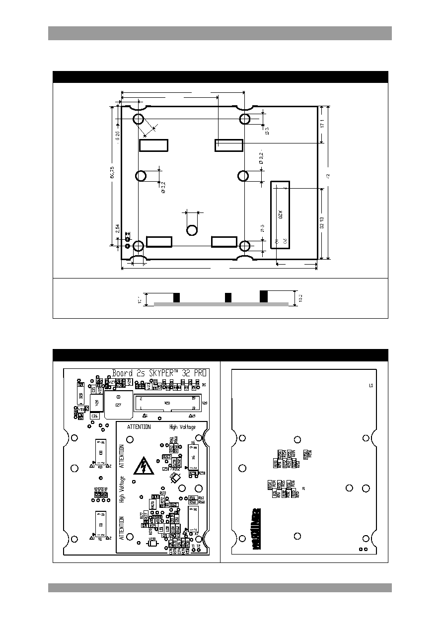
Dimensions
Dimensions in mm
ÿ 1,3
ÿ
3
X10
18,25
45,75
57,8
2
1
10
9
92
7,8
ÿ 3
ÿ 3,2
Component Placement Layout
Evaluation Board
Board 2s SKYPERTM 32PRO -
Technical Explanations
5 / 11
2005-06-08 ≠ Rev02
© by
SEMIKRON
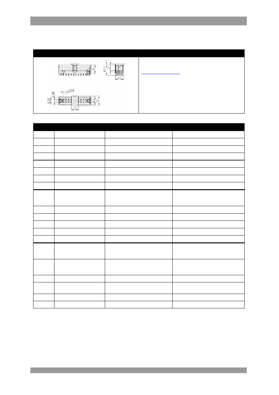
PIN Array
(not SKiiPÆ compatible)
Connector X20 (ODU FLAKAFIX 511.068.803.020)
Product information of suitable female connectors and
distributor contact information is available at e.g.
http://www.harting.com
(part number 09 18 520 6 813).
PIN
Signal
Function
Specification
X20:01
IF_PWR_15P
Drive power supply
Stabilised +15V ±4%
X20:02
IF_PWR_GND
GND for power supply
X20:03
IF_PWR_15P
Drive power supply
Stabilised +15V ±4%
X20:04
IF_PWR_GND
GND for power supply
X20:05
IF_PWR_15P
Drive power supply
Stabilised +15V ±4%
X20:06
IF_PWR_GND
GND for power supply
X20:07 reserved
X20:08
IF_PWR_GND
GND for power supply
X20:09 IF_CMN_nHALT
Driver core status signal
(bidirectional signal with dominant
recessive behaviour)
Digital 15V logic;
LOW (dominant) = driver disabled;
HIGH (recessive) = ready to operate
X20:10 reserved
X20:11 reserved
X20:12
IF_CMN_GND
GND for signal IF_CMN_nHALT
X20:13 reserved
X20:14 reserved
X20:15
IF_HB_TOP
Switching signal input (TOP switch)
Digital 15 V logic; 10 kOhm impedance;
LOW = TOP switch off; HIGH = TOP
switch on
X20:16 IF_HB_BOT
Switching signal input (BOTTOM
switch)
Digital 15 V logic; 10 kOhm impedance;
LOW = BOT switch off; HIGH = BOT
switch on
X20:17 reserved
X20:18 IF_HB_GND
GND for signals IF_HB_TOP &
IF_HB_BOT
X20:19 reserved
X20:20 reserved

Board 2s SKYPERTM 32PRO -
Technical Explanations
6 / 11
2005-06-08 ≠ Rev02
© by
SEMIKRON
Signal IF_CMN_nHALT
The Halt Logic Signals PRIM_HALT_IN and PRIM_HALT_OUT of the driver core are coupled to one bidirectional
signal (IF_CMN_nHALT) with dominant recessive behaviour. IF_CMN_nHALT shows the driver core status.
When IF_CMN_nHALT is HIGH (recessive), the driver core is ready to operate. When IF_CMN_nHALT is LOW
(dominant), the driver core is disabled / not ready to operate because of e. g. detected failure or driver core
system start.
A controller can hold with the IF_CMN_nHALT signal the driver core in a safe state (e.g. during a start up of a
system or gathered failure signal of other hardware) or generate a coeval release of paralleled driver.
Furthermore, paralleled drivers can send and receive IF_CMN_nHALT signals among each other by using a
single-wire bus.
Connection IF_CMN_nHALT
Setting Dead Time
DT adjustment
Designation Pattern
Name
Setting
R43
(connected to GND)
0603
PRIM_CFG_TDT2_IN
Factory setting: 0
R44
(connected to GND)
0603
PRIM_CFG_SELECT_IN
Factory setting: not equipped
R45
(connected to GND)
0603
PRIM_CFG_TDT3_IN
Factory setting: 0
R46
(connected to GND)
0603
PRIM_CFG_TDT1_IN
Factory setting: not equipped
Factory setting: 4µs
Setting Dynamic Short Circuit Protection
R
CE
& C
CE
Designation Pattern
Name
Setting
R162 1206
R
CE
Factory setting: not equipped
TOP
C150 1206
C
CE
Factory setting: not equipped
TOP
R262 1206
R
CE
Factory setting: not equipped
BOT
C250 1206
C
CE
Factory setting: not equipped
BOT
Board 2s SKYPERTM 32PRO -
Technical Explanations
7 / 11
2005-06-08 ≠ Rev02
© by
SEMIKRON
Collector Series Resistance
R
VCE
Designation Pattern
Name
Setting
R150 MiniMELF
R
VCE
*
Factory setting: not equipped
TOP
R250 MiniMELF
R
VCE
*
Factory setting: not equipped
BOT
* 1200V IGBT operation: 0
*
1700V IGBT operation: 1k / 0,4W
Adaptation Gate Resistors
R
Gon
& R
Goff
Designation Pattern
Name
Setting
R151, R152, R153
(parallel connected)
MiniMELF
R
Gon
Factory setting: not equipped
TOP
R154, R155, R156
(parallel connected)
MiniMELF
R
Goff
Factory setting: not equipped
TOP
R251, R252, R253
(parallel connected)
MiniMELF
R
Gon
Factory setting: not equipped
BOT
R254, R255, R256
(parallel connected)
MiniMELF
R
Goff
Factory setting: not equipped
BOT
Setting Soft Turn-Off
R
Goff_SC
Designation Pattern
Name
Setting
R160, R161
(parallel connected)
MiniMELF
R
Goff_SC
Factory setting: not equipped
TOP
R260, R261
(parallel connected)
MiniMELF
R
Goff_SC
Factory setting: not equipped
BOT
Temperature Signal
The temperature sensor inside the SEMiX
Æ
module is directly connected to contacting points T1 and T2. For
details to the temperature sensor, see Modules Explanations SEMiX
Æ
.
Safety Warnings:
The contacting points T1 and T2 are not electrical isolated. Due to high voltage that may be present at the
contacting points T1 and T2, some care must be taken in order to avoid accident. There is no cover or potential
isolation that protect the high voltage sections / wires from accidental human contact.
Board 2s SKYPERTM 32PRO -
Technical Explanations
8 / 11
2005-06-08 ≠ Rev02
© by
SEMIKRON
Over Temperature Protection Circuit (OTP)
The external error input SEC_TOP_ERR_IN on the secondary side (high potential) of the driver core is used for
an over temperature protection circuit to place the gate driver into halt mode.
Dimensioning OTP
1. Define an over temperature trip level according to the application.
2. Calculate the nominal ohmic resistance value of the temperature sensor at the defined trip
level (see "Modules ≠ Explanations - SEMiX
Æ
" on SEMiX
Æ
product overview page at
http://www.semikron.com
).
3. The trip level on the adapter board is set with R172 by using the calculated resistance value.
Factory setting R172: not equipped
If no resistor is used, a failure signal is generated.
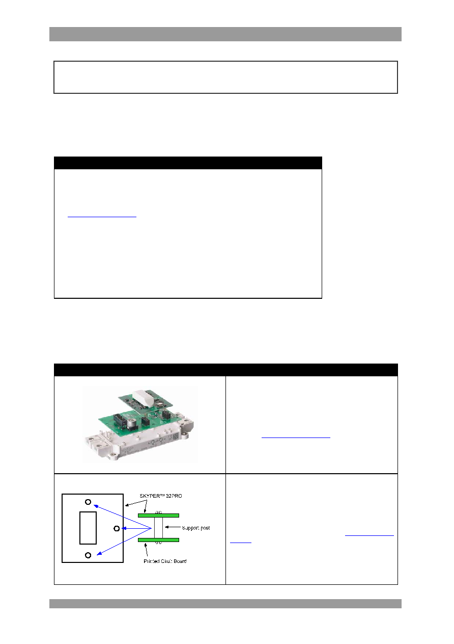
Mounting Notes
The electrical connections between evaluation board and SEMiX
Æ
are realised via spring contacts integrated in
SEMiX
Æ
power modules and via landing pads on the bottom side of the evaluation board.
Evaluation Board & Driver Core Mounting
1. Soldering of components (e.g. R
Gon
, R
Goff
, etc.) on
adapter board.
2. Evaluation Board has to be fixed to the SEMiX
Æ
module
(see "Mounting Instruction and Application Notes
for SEMiX
Æ
IGBT modules" on SEMiX
Æ
product overview
page at
http://www.semikron.com
).
3. Insert driver core into the box connector on evaluation
board.
The connection between driver core and evaluation board
should be mechanical reinforced by using support posts.
The posts have to be spaced between driver core and
evaluation board.
Product information of suitable support posts and distributor
contact information is available at e.g.
http://www.richco-
inc.com
(part number MSPM-8-01).
Please note:
If the contacting points T1 and T2 are used for evaluation of the temperature sensor, the Over Temperature Protection
Ciruit must be disabled by taking out the resistors R175, R178 and R179.
Board 2s SKYPERTM 32PRO -
Technical Explanations
9 / 11
2005-06-08 ≠ Rev02
© by
SEMIKRON
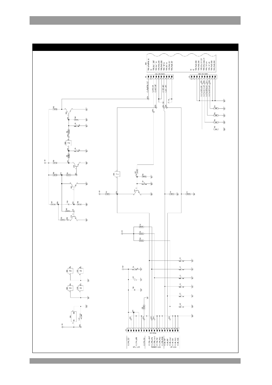
Schematics
Schematic I Evaluation Board

Board 2s SKYPERTM 32PRO -
Technical Explanations
10 / 11
2005-06-08 ≠ Rev02
© by
SEMIKRON
Schematic II Evaluation Board

Board 2s SKYPERTM 32PRO -
Technical Explanations
11 / 11
2005-06-08 ≠ Rev02
© by
SEMIKRON
Layouts
Primary & Secondary Layout
Parts List
Parts List Evaluation Board
Count
Ref. Designator
Value
Pattern Name
Description
8
C170, C171, C173, C174, C175,
C176, CD20, CN170
100nF
0805 (SMD)
Capacitor X7R
6
C20, C21, C22, C23, C24, C25
1nF
0805 (SMD)
Capacitor X7R
1
C26
2,2µF
1210 (SMD)
Capacitor X7R
1
C27
220uF/35V
SMD
Longlife-Elko
1
C31
68pF
0603 (SMD)
Capacitor NP0
2
C35, C151
1uF
1206 (SMD)
Capacitor X7R
1
C36
100pF
0603 (SMD)
Capacitor NP0
1
D20
74C14
SOIC 14 (SMD)
Logic-IC 74C...
2
L150, L151
100uH
SIMID02 (SMD)
Inductor
1
N170
LM2904
SOIC 8 (SMD)
Operational Amplifier
2
R157, R171
15,0KOhm
0603 (SMD)
1%
1
R158
10,0Ohm
0603 (SMD)
1%
2
R163, R263
10,0KOhm
MiniMelf (SMD)
1%
3
R170, R174, R176
30,1KOhm
0603 (SMD)
1%
1
R175
5,62KOhm
MiniMelf (SMD)
1%
1
R177
3,01KOhm
1206 (SMD)
1%
2
R178, R179
0,00Ohm
MiniMelf (SMD)
3
R28, R50, R52
10,0KOhm
MikroMelf (SMD)
1%
6
R30, R31, R32, R33, R34, R37
5,11KOhm
MikroMelf (SMD)
1%
1
R36
3,32KOhm
0603 (SMD)
1%
2
R43, R45
0,00Ohm
0603 (SMD)
3
R47, R54, R56
10,0KOhm
0603 (SMD)
1%
1
R51
121KOhm
0603 (SMD)
1%
1
R53
100Ohm
MikroMelf (SMD)
1%
1
R57
1,50KOhm
MikroMelf (SMD)
1%
1
R58
1,00KOhm
0603 (SMD)
1%
2
R60, R61
2,00KOhm
0603 (SMD)
1%
1
R62
3,92KOhm
0603 (SMD)
1%
2
V150, V250
BY203/20S
High Voltage Diode
2
V170, V171
BAV70W
SOT323 (SMD)
Double Diode
1
V20
SMCJ15
DO214AB (SMD)
Suppressor Diode
5
V23, V25, V26, V27, V29
BC847B
SOT23 (SMD)
NPN-Transistor
1
V28
BZX284-C7V5
SOD110 (SMD)
Zener-Diode
1
X20
20p.
SMD
Connector
4
X6, X7, X10, X11
RM2,54 10p.
SMD
Box Connector
TP: Test Point
Box Connector: SUYIN 254100FA010G200ZU