1N6102A
Thru
1N6137A
TEL:805-498-2111 FAX:805-498-3804
© 1997 SEMTECH CORP.
652 MITCHELL ROAD NEWBURY PARK CA 91320
QPL
500 Watt Axial Leaded TVS
FEATURES:
∑
500 Watts Peak Pulse Power (tp = 10/1000µs)
∑
Voidless hermetically sealed glass package
∑
Metallurgically bonded
∑
High surge capacity
∑
Military & Industrial applications
∑
Available in
JAN, JTX, and JTXV versions per
MIL-S-19500/516
DESCRIPTION
The 1N61xx series of transient voltage suppressors are
designed to protect military and commercial electronic
equipment from overvoltages caused by lightning, ESD,
EFT, inductive load switching, and EMP. These devices are
constructed using two p-n junction TVS diodes in a back-to-
back configuration, hermetically sealed in a voidless glass
package. The hermetically sealed package provides high
reliability in harsh environmental conditions. TVS diodes
are further characterized by their high surge capability, low
operating and clamping voltages, and a theoretically
instantaneous response time. This makes them ideal for
use as board level protection for sensitive semiconductor
components.
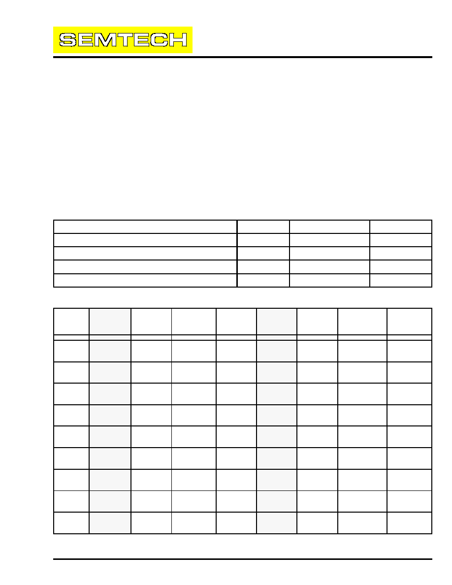
MAXIMUM RATINGS
RATING
SYMBOL
VALUE
UNIT
Peak Pulse Power (tp = 10 x 1000µs)
Ppk
500
Watts
Operating Temperature
Tj
-65 to +175
∞C
Storage Temperature
Tstg
-65 to +175
∞C
Steady-State Power Dissipation @ TL = 75∫C (3/8")
PD
3
Watts
MECHANICAL CHARACTERISTICS:
∑
Hermetically sealed glass package
∑
Tinned copper leads
∑
Marking : P/N, date code, logo
ELECTRICAL CHARACTERISTICS @ 25∞C (unless otherwise specified)
DEVICE
TYPE
REVERSE
STAND-OFF
VOLTAGE
V
RWM
REVERSE
LEAKAGE
CURRENT
I
R
MINIMUM
BREAKDOWN
VOLTAGE
V
BR
@ I
T
TEST
CURRENT
I
T
MAXIMUM
CLAMPING
VOLTAGE
VC @ I
PP
PEAK PULSE
CURRENT
Ipp
tp = 1ms
TEMPERATURE
COEFFICIENT
OF V
BR
Vz
MAXIMUM
REVERSE
LEAKAGE
CURRENT (Ir2)
TA=+150∞C
(V)
(µA)
(V)
(mA)
(V)
(A)
% / ∞C
(A)
1N6102A
5.2
100
6.46
175
10.5
47.6
0.05
4000
1N6103A
5.7
50
7.13
175
11.2
44.6
0.06
750
1N6104A
6.2
20
7.79
150
12.1
41.3
0.06
500
1N6105A
6.9
20
8.65
150
13.4
37.3
0.06
300
1N6106A
7.6
20
9.50
125
14.5
34.5
0.07
200
1N6107A
8.4
20
10.45
125
15.6
32.0
0.07
200
1N6108A
9.1
20
11.40
100
16.9
29.6
0.07
150
1N6109A
9.9
20
12.35
100
18.2
27.5
0.08
150
1N6110A
11.4
20
14.25
75
21.0
23.8
0.08
100
1N6111A
12.2
20
15.20
75
22.3
22.4
0.08
100
1N6112A
13.7
1
17.10
65
25.1
19.9
0.085
100
1N6113A
15.2
1
19.0
65
27.7
18.0
0.085
100
1N6114A
16.7
1
20.9
50
30.5
16.4
0.085
100
1N6115A
18.2
1
22.8
50
33.3
15.0
0.09
100
1N6116A
20.6
1
25.7
50
37.4
13.4
0.09
100
1N6117A
22.8
1
28.5
40
41.6
12.0
0.09
100
1N6118A
25.1
1
31.4
40
45.7
10.9
0.095
100
1N6119A
27.4
1
34.2
30
49.9
10.0
0.095
100
1N6120A
29.7
1
37.1
30
53.6
9.3
0.095
100
1N6121A
32.7
1
40.9
30
59.1
8.5
0.095
100
1N6122A
35.8
1
44.7
25
64.6
7.7
0.095
100
1N6123A
38.8
1
48.5
25
70.1
7.1
0.095
100
1N6124A
42.6
1
53.2
20
77.0
6.5
0.095
100
1N6125A
47.1
1
58.9
20
85.3
5.9
0.100
100
1N6126A
51.7
1
64.6
20
97.1
5.1
0.100
100
1N6127A
56.0
1
71.3
20
103.1
4.8
0.100
100
1N6128A
62.2
1
77.9
15
112.8
4.4
0.100
100
1N6129A
69.2
1
86.5
15
125.1
4.0
0.100
100
1N6130A
76.0
1
95.0
12
137.6
3.6
0.100
100
1N6131A
83.6
1
104.5
12
151.3
3.3
0.100
100
1N6132A
91.2
1
114.0
10
165.1
3.0
0.100
100
1N6133A
98.8
1
123.5
10
178.8
2.8
0.105
100
1N6134A
114.0
1
142.5
8
206.3
2.4
0.105
100
1N6135A
121.6
1
152.0
8
218.4
2.3
0.105
100
1N6136A
136.8
1
171.0
5
245.7
2.0
0.110
100
1N6137A
152.0
1
190.0
5
273.0
1.8
0.110
100
1. Non-A Part has 5% higher clamping voltage, 5% lower minimum breakdown voltage, and 5% lower peak pulse current.

1N6102A
Thru
1N6137A
TEL:805-498-2111 FAX:805-498-3804
© 1997 SEMTECH CORP.
652 MITCHELL ROAD NEWBURY PARK CA 91320
QPL
500 Watt Axial Leaded TVS
AMBIENT TEMPERATURE (TA) IN degC
MAX. POWER (W)
0
0.5
1
1.5
2
2.5
0
20
40
60
80
100
120
140
160
180
100
60
40
20
0
Pulse conditions as
defined by 10 X 1000us
0
40
80
120
160
200
Pp or
Ipp in %
of max
ratings
Tj (oC)
impulse waveform
A
D
B
B
C
NOTE
N
DIM
MAX
MIN
MAX
MIN
INCHES
MM
DIMENSIONS
A
B
C
D
2
0.140
1.300
1.00
0.026
0.033
0.66
0.84
0.085
2.1
3.6
25.4
33.0
0.245
0.140
3.5
6.3
NOTES :
1. Controlling dimension is inches.
2. Includes uncontrolled area of device leads.
PEAK PULSE POWER vs. PULSE TIME
10x1000µs IMPULSE WAVEFORM
PULSE DERATING CURVE
STEADY STATE DERATING CHARACTERISTICS
FOR FREE AIR MOUNTING
MECHANICAL OUTLINE
SCHEMATIC
0.1
1
10
100
0.1
1
10
100
1000
10000
Pulse Duration (us)
Ppp - Peak Pulse Power (kW)

