 | –≠–ª–µ–∫—Ç—Ä–æ–Ω–Ω—ã–π –∫–æ–º–ø–æ–Ω–µ–Ω—Ç: LC04-12 | –°–∫–∞—á–∞—Ç—å:  PDF PDF  ZIP ZIP |

PROTECTION PRODUCTS
1
www.semtech.com
PROTECTION PRODUCTS
LC04-12
Dual Low Capacitance TVS Array
for Telecom Line-Card Applications
u
Transient protection for high-speed data lines to
Bellcore GR 1089 I
PP
=100A (2/10µs)
ITU K.20 I
PP
=100A (5/310µs)
IEC 61000-4-2 (ESD) 15kV (air), 8kV (contact)
IEC 61000-4-5 (Lightning) I
PP
=100A (8/20µs)
u
Protects two tip and ring line pairs
u
Low capacitance for high-speed interfaces
u
High surge capability
u
Low clamping voltage
u
Solid-state silicon avalanche technology
Description
Features
Circuit Diagram
Schematic & PIN Configuration
Revision 9/2000
Applications
Mechanical Characteristics
SO-16 (Top View)
u
JEDEC SO-16 package
u
Molding compound flammability rating: UL 94V-0
u
Marking : Part number, date code, logo
u
Packaging : Tube or Tape and Reel per EIA 481
u
ADSL/HDSL
u
RS-232 & RS-423
u
V.90
u
WAN/LAN Equipment
u
Cable Modems
TIP
RING
The LC04-12 has been specifically designed to protect
sensitive components which are connected to high-
speed telecommunications lines from over voltages
caused by lightning, ESD (electrostatic discharge), and
EFT (electrical fast transients).
The device is in a JEDEC SO-16 NB package. It is
designed to provide metallic (Tip to Ring) or common
mode (Tip to Ground & Ring to Ground) surge protec-
tion for up to two Tip and Ring pairs. The low capaci-
tance topology means signal integrity is preserved on
high-speed lines. The high surge capability (600W,
tp=10/1000µs) makes the LC04-12 suitable for
telecommunications systems operating in harsh tran-
sient environments. The LC04-12 is designed to meet
the lightning surge requirements of Bellcore GR-
1089(intra-building), ITU K.20, and IEC 61000-4-5.
The features of the LC04-12 are ideal for protecting
ADSL, RS-232, RS-423, RS-422, and V.90 interfaces.

2
„ 2000 Semtech Corp.
www.semtech.com
PROTECTION PRODUCTS
LC04-12
Absolute Maximum Rating
Electrical Characteristics
g
n
it
a
R
l
o
b
m
y
S
e
u
l
a
V
s
ti
n
U
)
s
µ
0
0
0
1
/
0
1
=
p
t(
r
e
w
o
P
e
s
l
u
P
k
a
e
P
P
k
p
0
0
6
s
tt
a
W
1
=
p
t(
t
n
e
rr
u
C
e
s
l
u
P
k
a
e
P
µ
0
0
0
1
/
0
)
s
I
P
P
5
2
A
)
s
µ
0
2
/
8
=
p
t(
t
n
e
rr
u
C
e
s
l
u
P
k
a
e
P
I
P
P
0
0
1
A
e
r
u
t
a
r
e
p
m
e
T
g
n
ir
e
d
l
o
S
d
a
e
L
T
L
).
c
e
s
0
1
(
0
6
2
C
∞
e
r
u
t
a
r
e
p
m
e
T
g
n
it
a
r
e
p
O
T
J
5
2
1
+
o
t
5
5
-
C
∞
e
r
u
t
a
r
e
p
m
e
T
e
g
a
r
o
t
S
T
G
T
S
0
5
1
+
o
t
5
5
-
C
∞
2
1
-
4
0
C
L
r
e
t
e
m
a
r
a
P
l
o
b
m
y
S
s
n
o
it
i
d
n
o
C
m
u
m
i
n
i
M
l
a
c
i
p
y
T
m
u
m
i
x
a
M
s
ti
n
U
e
g
a
tl
o
V
ff
O
-
d
n
a
t
S
e
s
r
e
v
e
R
V
M
W
R
2
1
V
e
g
a
tl
o
V
n
w
o
d
k
a
e
r
B
e
s
r
e
v
e
R
V
R
B
I
t
A
m
1
=
3
.
3
1
V
t
n
e
rr
u
C
e
g
a
k
a
e
L
e
s
r
e
v
e
R
I
R
V
M
W
R
C
∞
5
2
=
T
,
V
2
1
=
2
A
µ
e
g
a
tl
o
V
g
n
i
p
m
a
l
C
V
C
I
P
P
,
A
0
1
=
s
µ
0
0
0
1
/
0
1
=
p
t
5
.
9
1
V
e
g
a
tl
o
V
g
n
i
p
m
a
l
C
V
C
I
P
P
,
A
5
2
=
s
µ
0
0
0
1
/
0
1
=
p
t
4
2
V
e
c
n
a
ti
c
a
p
a
C
n
o
it
c
n
u
J
C
j
e
n
i
L
h
c
a
E
V
R
z
H
M
1
=
f
,
V
0
=
5
1
F
p

3
„ 2000 Semtech Corp.
www.semtech.com
PROTECTION PRODUCTS
PROTECTION PRODUCTS
LC04-12
Typical Characteristics
Non-Repetitive Peak Pulse Power vs. Pulse Time
Power Derating Curve
Clamping Voltage vs. Peak Pulse Current
(tp=8/20ms)
0
10
20
30
40
50
60
70
80
90
100
110
0
5
10
15
20
25
30
Time (
µ
s)
Percent of I
PP
e
-t
td = I
PP
/2
Waveform
Parameters:
tr = 8
µ
s
td = 20
µ
s
Pulse Waveform
Clamping Voltage vs. Peak Pulse Current
(tp=10/1000ms)
0.1
1
10
100
0.1
1
10
100
1000
Pulse Duration - tp (
µ
s)
P
eak P
u
l
se P
o
wer - P
PP
(kW)
0
5
10
15
20
25
0
20
40
60
80
100
120
140
160
Peak Pulse Current - Ipp (A)
Clamping Voltage - Vc (V)
Waveform
Parameters:
tr = 8
µ
s
td = 20
µ
s
0
5
10
15
20
25
30
0
5
10
15
20
25
30
Peak Pulse Current - Ipp (A)
Clamping Voltage - Vc (V)
Waveform
Parameters:
tr = 10
µ
s
td = 1000
µ
s
0
10
20
30
40
50
60
70
80
90
100
110
0
25
50
75
100
125
150
Ambient Temperature - T
A
(
o
C)
%
of
R
a
t
e
d P
o
wer or I
PP
4
„ 2000 Semtech Corp.
www.semtech.com
PROTECTION PRODUCTS
LC04-12
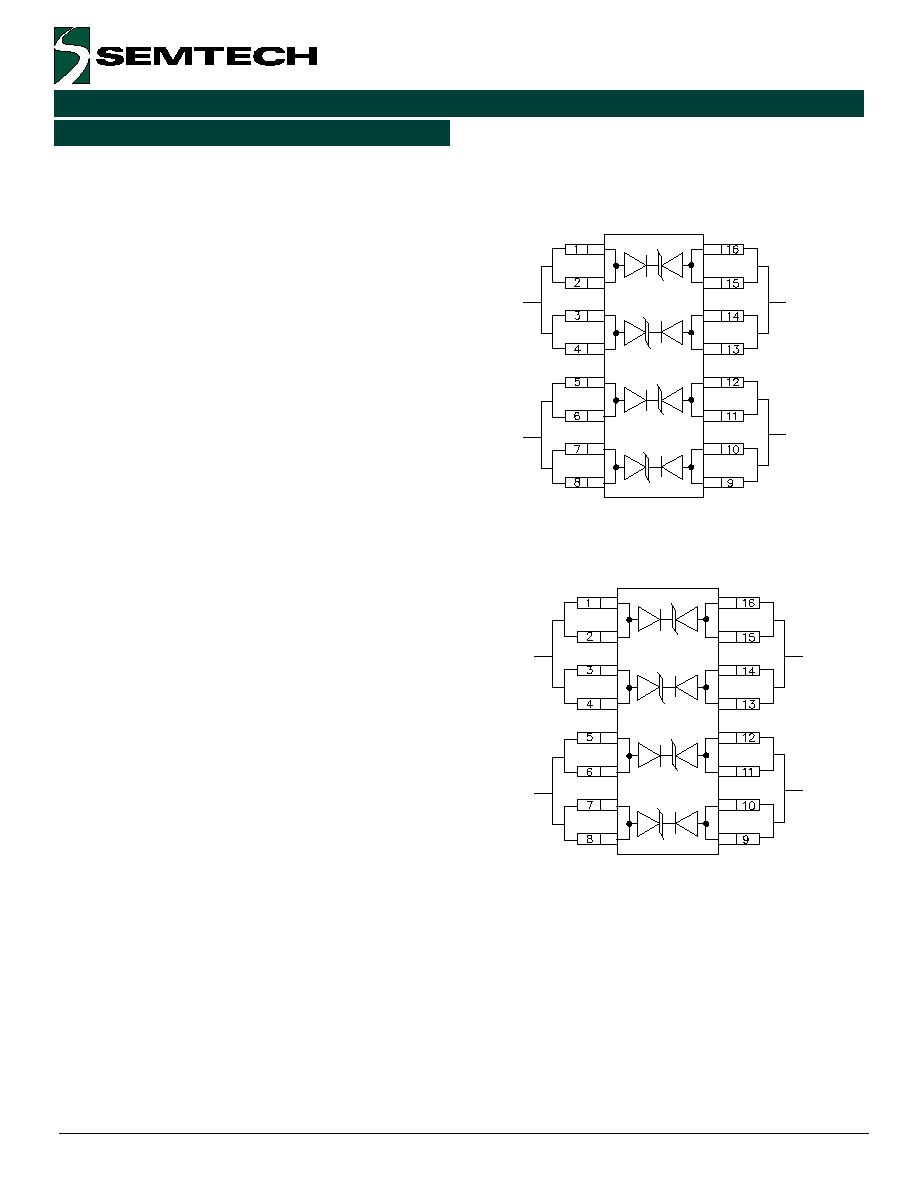
Figure 1 - Connection for Differential (Line-to-Line)
Protection of two Tip/Ring Line Pairs
TIP 1
TIP 2
RING 1
RING 2
Device Connection Options
The LC04-12 is designed to protect up to four high-
speed data lines (two differential pairs) from transient
over-voltages which result from lightning and ESD.
Differential protection of two line pairs is achieved by
connecting the device as follows (Figure 1): Pins 1-4
are connected to line 1 of the first pair (i.e. Tip 1) and
pins 13-16 are connected to line 2 of the first pair (i.e.
Ring 1). Pins 5-8 are connected to line 1 of the second
pair (i.e. Tip 2) and pins 9-12 are connected to line two
of the second pair (i.e. Ring 2).
Common mode protection of one line pair is achieved
by connecting the device as shown in Figure 2. The
protected lines are connected at pins 1-4 and pins 9-
12. connection to ground is made at pins 5-8 and 13-
16. optionally, the lines may be connected at pins 1-4
and 5-8 with pins 9-16 being connected to ground.
All pins should be connected for best results. Minimize
parasitic inductance in the protection circuit path by
keeping the trace length between the protected line
and the LC04-12 as short as possible. Ground con-
nections should be made directly to the ground plane.
ADSL Protection
Configuring The LC04-12 for Remote Terminal ADSL
Applications
A typical ADSL protection circuit for remote terminals is
shown in Figure 3. The LC04-12 is connected between
Tip & Ring on the transmit and receive line pairs. It
provides protection to common mode (line-to-ground)
lightning and ESD surges. It is designed to meet the
intra-building requirements of Bellcore GR-1089. To
complete the protection circuit, the LCDA12C-1 is
employed as the IC side protection element. This
device helps prevent the transceiver from latching up
by providing fine clamping of transients that are
coupled through the transformer.
Figure 2 - Connection for Common Mode (Line-to-
Ground) Protection of one Tip/Ring Line Pair
TIP
GND
GND
RING
Applications Information

5
„ 2000 Semtech Corp.
www.semtech.com
PROTECTION PRODUCTS
PROTECTION PRODUCTS
LC04-12
Configuring The LC04-12 for Central Office ADSL
Applications
For Central Office applications, the LC04-12 can be
configured for operation to 24V with the addition of
two external steering diodes. This is accomplished by
connecting two adjacent legs of the LC04-12 in series
and adding the steering diodes as shown in Figure 4.
Each of the TVS diodes has a working voltage of 12V.
Since the voltages are additive when series connected,
the device will have a working voltage of 24V. The
power rating of the device is effectively doubled since
the surge current capability remains unchanged.
During positive duration transients, the internal TVS
diodes of the LC04-12 will be reversed biased when
the line voltage exceeds 24V. Transient current will
flow through the LC04-12 to ground. For negative
duration transient, the external steering diodes (D1 &
D2) will be forward biased when the voltage exceeds
the forward voltage (V
F
) of the device.
The steering diodes are required to insure that the
internal compensation diodes of the LC04-12 are not
reverse biased as this would result in their destruction.
The ES1A ultrafast rectifiers have been found to work
well in this application. These devices will survive the
Bellcore 1089 (intra-building) and ITU K.20/K.21
surges and have a repetitive reverse voltage rating of
50V, and a typical junction capacitance of 10pF.
The total capacitance seen by the line will typically be
<25pF. This is determined by the sum of the capaci-
tance of the steering diode and 1/2 of the capacitance
of each line pair of the LC04-12.
Applications Information (Continued)

6
„ 2000 Semtech Corp.
www.semtech.com
PROTECTION PRODUCTS
LC04-12
Typical Applications
Figure 3 - ADSL Protection (Remote Terminal)
Figure 4- LC04-12 Configured for 24V Lines (ADSL Central Office)
t
n
e
n
o
p
m
o
C
t
r
a
P
r
e
b
m
u
N
n
o
it
p
ir
c
s
e
D
S
V
T
2
1
-
4
0
C
L
e
c
n
a
ti
c
a
p
a
c
w
o
L
y
a
rr
a
e
d
o
i
d
S
V
T
2
D
&
1
D
A
1
S
E
e
c
a
f
r
u
s
t
s
a
f
a
rt
l
U
r
e
if
it
c
e
r
t
n
u
o
m

7
„ 2000 Semtech Corp.
www.semtech.com
PROTECTION PRODUCTS
PROTECTION PRODUCTS
LC04-12
Land Pattern - SO-16
Outline Drawing - SO-16

8
„ 2000 Semtech Corp.
www.semtech.com
PROTECTION PRODUCTS
LC04-12
Contact Information
Semtech Corporation
Protection Products Division
652 Mitchell Rd., Newbury Park, CA 91320
Phone: (805)498-2111 FAX (805)498-3804
t
r
a
P
r
e
b
m
u
N
g
n
i
k
r
o
W
e
g
a
tl
o
V
r
e
p
y
t
Q
l
e
e
R
e
z
i
S
l
e
e
R
B
T
.
2
1
-
4
0
C
L
V
2
1
0
0
5
h
c
n
I
7
E
T
.
2
1
-
4
0
C
L
V
2
1
0
0
5
2
h
c
n
I
3
1
Note:
(1) No suffix indicates tube pack.
Ordering Information