doc5-703-ir20-ds-101_draft07.qxd
SerialCoderTM IR UR5HC703-IR20
Extremely Low-Power Keyboard
Encoder Interfaces IrDA
SerialCoder is a trademark of Semtech
Corporation. All other trademarks belong to their
respective companies.
Copyright ©1999-2001 Semtech Corporation
DOC5-703-IR20-DS-101
www.semtech.com
1
HID & SYSTEM MANAGEMENT PRODUCTS, KEYCODERTM FAMILY
DESCRIPTION
FEATURES
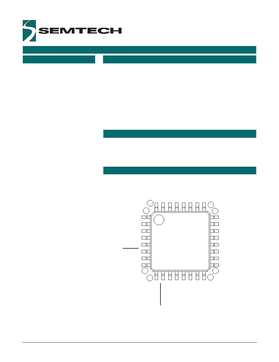
1
8
9
32
25
24
16
17
COL3
COL4
COL5
COL6
VDD2
RESET
VSS2
VDD
ROW6
ROW5
ROW4
ROW3
ROW2
ROW1
ROW0
COL15
OCSIN
OSCOUT
VSS
COL7
COL8
COL9
COL10
COL11
ROW7
COL12
TXD
COL13
COL14
COL0
COL1
COL2
UR5HC703-IR20-FG
LQFP
· 8 x 16 Matrix Encoding
· IC is independent of the keyboard
layout
· Extremely low-power operation,
transparent to the host
· Typical current consumption of
less than 1µA at room
temperature; 10µA at 85°C
· Robust algorithm for ghost-key
elimination
· CMOS output-only asynchronous
serial interface to the host using
standard IrDA
· 9600 Baud 8N1 serial data format
· Very simple serial protocol -- two-
byte identification string on
power-up; single-byte matrix-
position for each key-press or
key-release
· Low-cost wireless keyboard
solution
The SerialCoderTM IR UR5HC703-
IR20 is an extremely low-power, "off-
the-shelf" infrared serial keyboard
encoder. Robust, tiny and flexible,
the IC is a good match for any
application where a low-cost
wireless keyboard is attractive and
an IrDA host is available.
The IC provides extremely low-
power operation, transparent to the
host. Power consumption is
reduced to just the circuit's leakage
when all keys are released. The
typical current consumption is less
than 1µA at room temperature and
10µA at 85°C.
If a key or group of keys stays in the
depressed position for ten minutes
(with no other keyboard activity), the
IC shuts down to save power.
The SerialCoderTM IR is simple to
implement. It requires few external
components and utilizes a tiny, low-
profile 32-pin LQFP package that
measures 7mm x 7mm.
APPLICATIONS
· Infrared wireless keyboards
· Personal digital assistant (PDA)
keyboard
· Instrumentation
· Remote control
· Home entertainment or
automation
PIN ASSIGNMENTS
PRELIMINARY
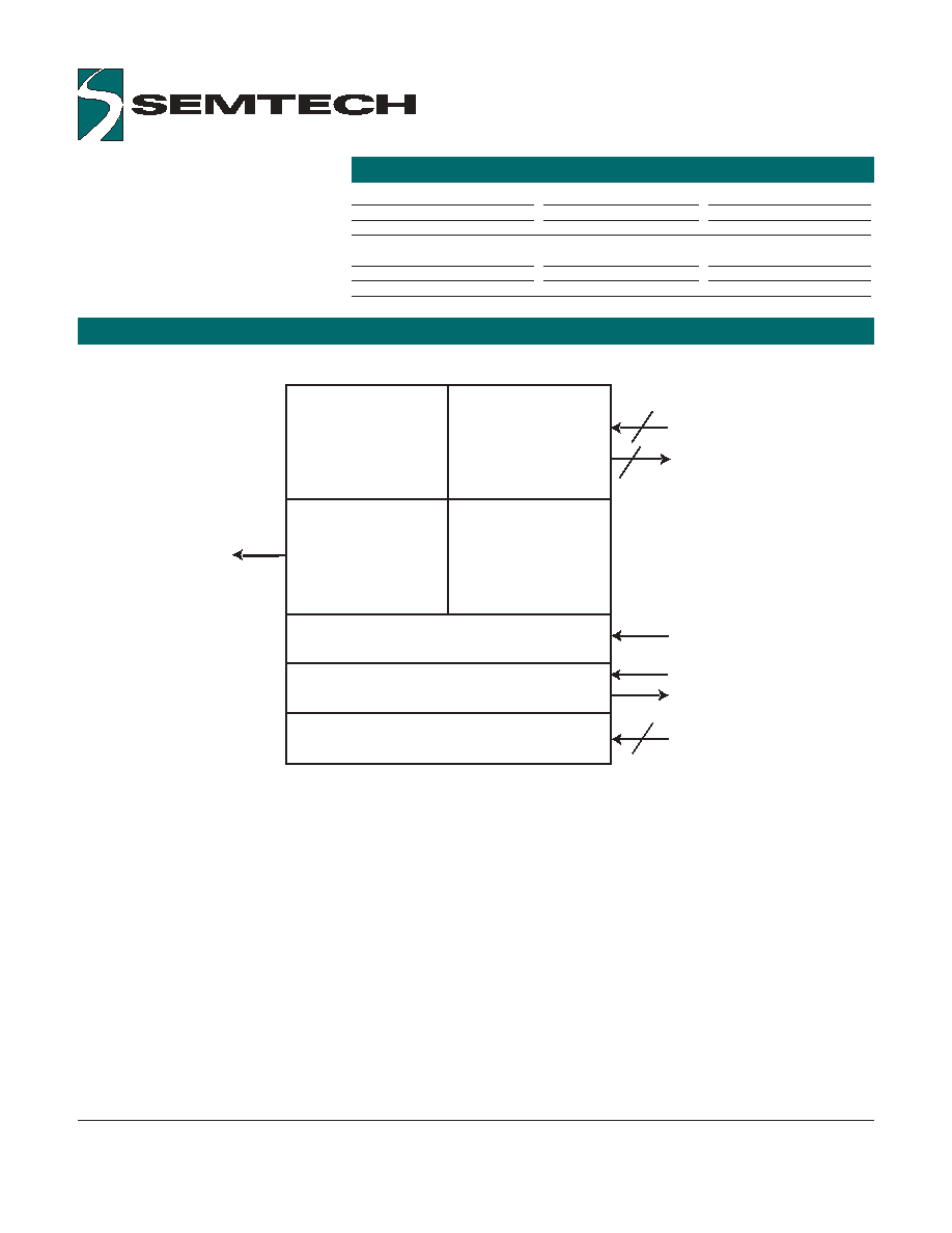
SERIALCODERTM IR UR5HC703-IR20 FUNCTIONAL DIAGRAM
ORDERING CODE
Copyright ©1999-2001 Semtech Corporation
DOC5-703-IR20-DS-101
www.semtech.com
2
TxD
4
Data
Buffer
Key
Matrix
Interface
Communication
Interface
Matrix
Scan Logic
Reset Logic
Oscillator
Power Supply
_RESET
OSCIN
_OSCOUT
8
16
R0-R7
C0-C15
Package Options
Pitch
Ta = -20° C to +85° C
32-pin plastic LQFP
0.8 mm
UR5HC703-IR20-FG
Other Materials
Type
Order number
UR5HC703-IR20 eval. kit
Evaluation kit
EVK5-703-IR20

PIN DEFINITIONS
Copyright ©1999-2001 Semtech Corporation
DOC5-703-IR20-DS-101
www.semtech.com
3
Mnemonic
Pin #
Type
Name and Function
Power Supply
V
DD
, V
DD
2
8,5
PWR
Positive supply voltage
V
SS
, V
SS
2
11,7
PWR
Negative power Supply:
signal ground
Reset
_RESET
6
I
Hardware reset pin: Reset Input
for orderly start-up. Low logic level is
required whenever V
DD
is below
minimum operating voltage
Oscillator pins
OSCIN
9
I
Oscillator input: Connect ceramic
resonator with built-in load capacitors
or CMOS clock from external oscillator
2 MHz operating frequency
_OSCOUT
10
O
Oscillator output: Connect
ceramic resonator with built-in load
capacitors or keep open if external
oscillator is used
Host Interface
TxD
27
O
Serial data output: Idle at high
voltage (logical 1), non-inverted data;
4µs pulsed output per IrDA timing
specification
Scanned
matrix pins
ROW0-ROW7
18-25
I
Row matrix inputs with pulsed
pull-up current sources
COL0-COL15
30-32,
O
Column matrix output, open drain
1-4,
12-16,
26, 28,
29, 17
Note: An underscore before a pin mnemonic denotes an active low signal.

Copyright ©1999-2001 Semtech Corporation
DOC5-703-IR20-DS-101
www.semtech.com
4
"GHOST" KEYS
In any scanned contact switch
matrix, whenever three keys
defining a rectangle on the switch
matrix are pressed at the same
time, a fourth key positioned on the
fourth corner of the rectangle is
sensed as being pressed. This is
known as the "ghost" or "phantom"
key problem.
Figure 1: "Ghost" or "Phantom" Key
Problem
Although the problem cannot be
totally eliminated without using
external hardware, there are
methods to neutralize its negative
effects for most practical
applications. Keys that are
intended to be used in
combinations should be placed in
the same row or column of the
matrix, whenever possible. Shift
keys (Shift, Alt, Ctrl, Window)
should not reside in the same row
(or column) as any other keys. The
SerialCoderTM IR has built-in
mechanisms to detect the
presence of "ghost" keys.
Actual key presses
"Ghost"
Key
KEYBOARD SCANNER
The encoder scans a keyboard organized as an 8 row by 16 column matrix
for a maximum of 128 keys. Smaller size matrixes can also be
accommodated by simply leaving unused pins open. The
SerialCoderTM IR provides internal pull-ups for the row input pins. When
active, the encoder selects one of the column lines (C0-C15) every 512 µS
and then reads the row data lines (R0-R7). A key closure is detected as a
zero in the corresponding position of the matrix.
A complete scan cycle for the entire keyboard takes approximately 9.2 ms.
Each key found pressed is debounced for a period of 20 ms. Once the
key is verified, the corresponding key code(s) are loaded into the transmit
buffer of the serial communication channel.
N-key rollover means the code(s) corresponding to each key press are
transmitted to the host system as soon as that key is debounced, indepen-
dent of the release of other keys.
When a key is released, the corresponding break code is transmitted to the
host system. Several keys can be held pressed at the same time.
However, if two or more key closures occur within a time interval of less
than 5 ms, an error flag is set, and those closures are not processed. This
feature protects against the effects of accidental key presses.
The SerialCoderTM IR achieves uniquely low system power consumption
thanks to Self-Power ManagementTM, which powers down the IC between
key presses. A key press wakes up the IC immediately without losing any
key data.
N-KEY ROLLOVER
POWER MANAGEMENT
PROTOCOL
Copyright ©1999-2001 Semtech Corporation
DOC5-703-IR20-DS-101
www.semtech.com
5
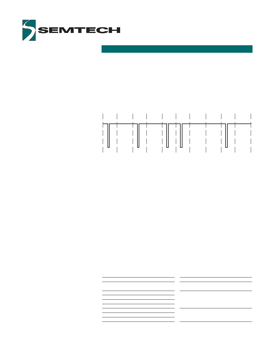
Serial transmission rate is 9600 Baud, with 8 data bits, no parity, least
significant bits transmitted first, idle/stop level high (logical 1), start bit level
low (logical 0), non-inverted data. Each bit with a zero value, including the
start bit, is indicated by a four-microsecond low pulse of the TxD line
toward the beginning of the time slot for the bit.
Infrared signals are based on the Infrared Data Association (IrDA)
Serial
Infrared Physical Layer Specification
. The diagram below shows the
electrical wave form of a single transmitted byte, 0x65. (Note that pulse
width is not to scale.)
Within 5ms after power-up, the IC sends a two-byte identification string of
0xF9, 0xFB. These two bytes are transmitted only once after each
power-up or reset of the IC.
These two ID values also represent key release action in the locations
[row=1, column=15] and [row=3, column=15] on the key matrix. Since the
values of these bytes represent release action of the keys, extraneous
characters are never generated, even if synchronization between the driver
and IC is lost, or power fluctuations/erroneous resets are applied to the
chip. If logistics of the host software driver do not permit "shared" use of
the identification values 0xF9 and 0xFB, then the user is advised not to
incorporate keys in the locations [row=1, column=15] and
[row=3, column=15] for the key matrix design.
Subsequent single-byte transmissions indicate the row (0-7),
column (0-15), and press/release action for each change of the state of
every key. If the release of a key leaves all of the keys on the key matrix in
the released state, the release report for that key is sent twice. Two release
report bytes in a row for the same key are a signal to the host driver that
the keyboard is completely idle and all keys are up.
Keyboard Report Byte
Bit Number
b7
b6
b5
b4
b3
b2
b1
b0
Comment
0 for key press (make), 1 for key release
(break)
Column location in the key matrix
4-bit binary value (0-15)
Row location in the key matrix (0-7)
3-bit binary value (0-7)
0
Start
1
Data
0
Data
1
Data
0
Data
0
Data
1
Data
1
Data
0
Data
1
Stop