PS2Adapt
TM
UR6HCPS2-SP40
Converts PS/2 Data to Serial or SPI
PS2Adapt is a trademark of Semtech Corp. All
other trademarks belong to their respective
companies.
Copyright Semtech, 2000-2001
DOC6-PS2-SP40-DS-102
www.semtech.com
1
HID & SYSTEM MANAGEMENT PRODUCTS, PROTOCOL INTERPRETER FAMILY
DESCRIPTION
FEATURES
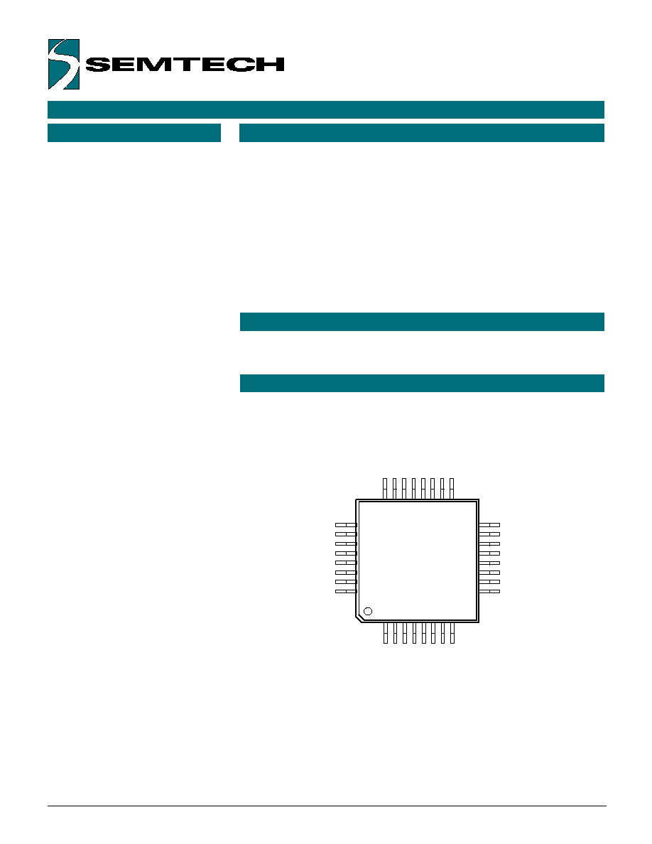
1
9
16
8
25
32
24
17
UR6HCPS2-SP40-FG
LQFP
CONF0
_CTS/_ATN
_PWR_OFF
SDATA
SCLK
TxD
RxD
E3DATA
OSCIN
_OSCOUT
VSS
LED3
LED2
LED1
LED0
RES0
CONF2
ASI/_SPI_SEL
X_PWR
VREF
_RESET
VSS2
VDD
_RTS/_SS
E0CLK
E0DATA
E1CLK
E1DATA
E2CLK
E2DATA
E3CLK
CONF1
� Typically consumes less than 1 �A
� Interfaces the host system via
either Asynchronous Serial
Interface or Serial Peripheral
Interface (SPI)
� Jumper selectable interface and
Baud rate
� Offers four PS/2 ports for the hot-
plug connection of external
keyboards or mice including
MouseWheel, 5 button mice and
absolute mode touch screens
� Easy to use, one way
communication protocol
� Operating voltage between 3
and 5 Volts
� Custom versions available in
small or large quantities
� Small 7x7 mm package to
accommodate slim designs
� H/PCs
� Web Phones
� PDAs
� System Legacy Support
The PS2Adapt
TM
is a Zero-Power
TM
protocol interpreter that can link an
AT/PS/2-compatible Human Input
Device (HID), such as a keyboard,
mouse, bar-code reader, etc. to any
host system equipped with either
Asynchronous Serial Interface (ASI)
or the Serial Peripheral Interface
(SPI).
The IC was designed specifically
for RISC-based portable devices
that are limited to ASI and SPI
interfaces. The PS2Adapt
TM
allows
designers to easily connect PS/2
devices to their system.
The UR6HCPS2-SP40 emulates all
the functions of the 8042 keyboard
controller which typically resides on
the AT/PS/2 motherboard. The
Zero-Power
TM
PS2Adapt
TM
will power
down even between
key presses and bewteen mouse
reports. Typical power
consumption is only 1 �A operating
between 3-5 Volts.
The UR6HCPS2-SP40 boasts 4
external PS/2 ports that support the
hot-plug connection of an external
PS/2 keyboard or mouse,
including MouseWheel, 5-button
mice and touch screens in absolute
mode.
Each of four external PS/2 ports
also support more than 140 key
scan codes including international
language keys, internet keys, and
power keys. The PS2Adapt
TM
also
offers 4 reserved pins for LED
functions, their functions can be
customized by Semtech.
APPLICATIONS
PIN ASSIGNMENTS
FUNCTIONAL DIAGRAM
ORDERING CODE
Copyright Semtech, 2002-2001
DOC6-PS2-SP40-DS-102
www.semtech.com
2
Package options
32-pin Plastic LQFP
Other materials
PS2Adapt
TM
Evaluation Kit
Pitch In mm's
0.8 mm
Part number
EVK6-PS2-SP40-100
TA = -40�C to +85�C
UR6HCPS2-SP40-FG
Power
Management
Unit
Dual Mode
Serial
Communications
Port
External
PS/2 Port 3
External
PS/2 Port 2
External
PS/2 Port 1
SCLK
RxD
TxD
SS/RTS
ATN/CTS
PWR_OFF
E2CLK
E2DATA
E3CLK
E3DATA
E1CLK
E1DATA
External
PS/2 Port 0
HID Manager
SDATA
ASI/_SPI_SEL
E0CLK
E0DATA
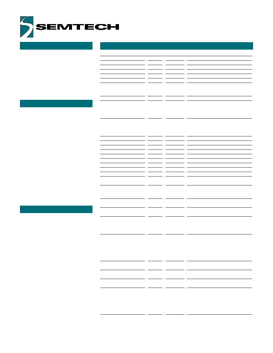
PIN DEFINITIONS
Pin Numbers
Mnemonic
LQFP
Type
Name and Function
Power Supply
VDD
8
PWR
Positive Supply Voltage: +3V-+5V
VREF
5
AI
Positive Analog Ref Voltage
VSS 11
PWR
Ground: analog signal
VSS2
7
PWR
Ground: negative supply voltage
_RESET
6
I
Hardware Reset Pin:
at Low-level, this pin holds the
UR6HCPS2-SP40 in a reset state.
Oscillator Pins
OSCIN
9
I
Oscillator input: connect ceramic
resonator with built-in load capacitors
or CMOS clock from external oscillator
4 MHz operating frequency
_OSCOUT
10
O
Oscillator Output: connect ceramic
resonator with built-in load capacitors
or keep open if external oscillator
is used
PS/2 Ports
E0CLK
18
I/nD
PS/2 Clock: for External Device 0
E0DATA
19
I/nD
PS/2 Data: for External Device 0
E1CLK
20
I/nD
PS/2 Clock: for External Device 1
E1DATA
21
I/nD
PS/2 Data: for External Device 1
E2CLK
22
I/nD
PS/2 Clock: for External Device 2
E2DATA
23
I/nD
PS/2 Data: for External Device 2
E3CLK
24
I/nD
PS/2 Clock: for External Device 3
E3DATA
25
I/nD
PS/2 Data: for External Device 3
System Status
Monitoring
_PWR_OFF
30
I�Int
Power Off Signal: capable of
Interrupt on both Positive and Negative
edges
X_PWR
4
AI
External PS/2 Device Power
Detector
Communication
Interface
_SS/_RTS
17
I_Int
Ready_To_Send: Active-Low
signal Input.Low-level indicates that
the Host System is ready to send
data from UR6HCPS2-SP40.
_ATN/_CTS
31
O
Attention (SPI Mode) or
Clear_To_Send (Asynchronous
Serial Mode ): Active-Low signal
Output. Low-level indicates that the
UR6HCPS2-SP40 has data to send to
the Host System
TXD
27
O
Transmit Data (Asynchronous
Serial Mode): Idle = "High" = 1
RXD
26
I
Receive Data (Asynchronous
Serial Mode): Reserved future use
SDATA
29
Master-In-Slave-Out (SPI Mode):
keep open for ASI mode or tie to Gnd
SCLK
28
I
Serial Clock (SPI Mode): in SPI
Mode, use the following Clock
sequence:Idle-high/ Negative-Edge
(Shift Data) \ Positive-Edge (Latch
Data), Idle-High. Keep open or tie to
Gnd for ASI mode
FUNCTIONAL DESCRIPTION
Copyright Semtech, 2002-2001
DOC6-PS2-SP40-DS-102
www.semtech.com
3
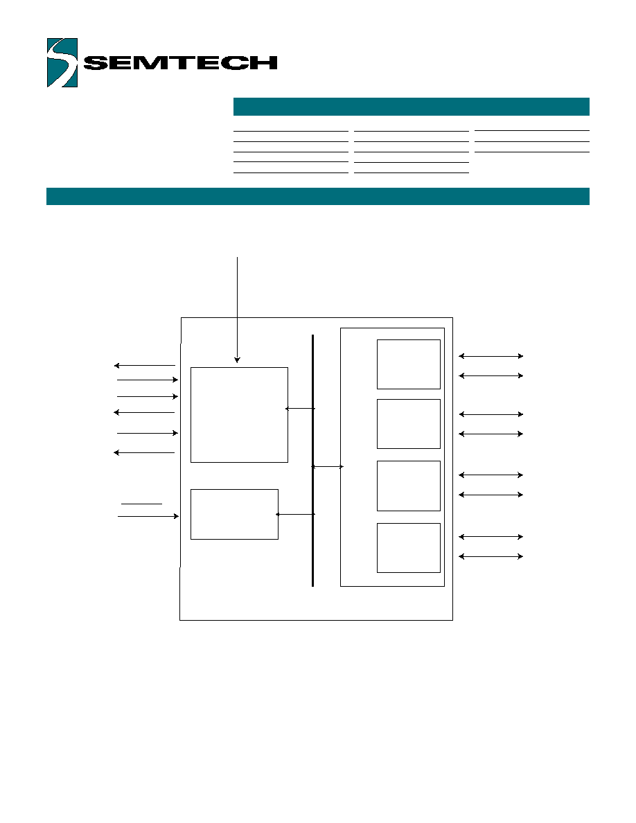
The PS2Adapt
TM
consists
functionally of three major sections.
These are the Dual Mode Serial
Communications Interface, the
Power Management Unit, and the
HID Manager. All sections
communicate with each other and
operate concurrently.
HID MANAGER
OPERATIONS BELOW 5 V
The UR6HCPS2-SP40 Human Input
Device (HID) Manager is
responsible for the configuration
and handling of HID devices that
are attached to the controller
through the four external PS/2 ports.
The HID Manager has the following
responsibilities:
1. Initialize PS/2 keyboards and
mice
2. Mix the information from external
PS/2 devices
3. Formatting and relaying reports of
the HID devices to the Host.
The standard PS/2 devices are
specified for supply voltage of 5V.
Operations of the UR6PS2-SP40 at
a lower voltage (3V) are only
possible if the HID devices
connected to ALL external PS/2
ports are capable of 3V operations.
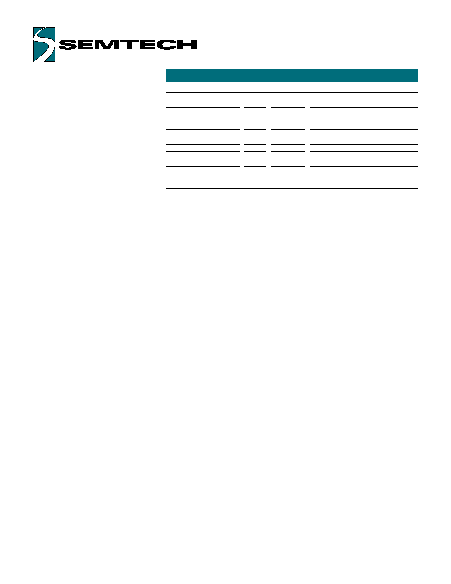
PIN DEFINITIONS, (CON'T)
Copyright Semtech, 2002-2001
DOC6-PS2-SP40-DS-102
www.semtech.com
4
Pin Numbers
Mnemonic
LQFP
Type
Name and Function
Configuration Pins
CONF0
32
I
Configuration pin 0; see Note 2
CONF1
1
I
Configuration pin 1; see Note 2
CONF2
2
I
Configuration pin 2; see Note 2
ASI/_SPI_SEL
3
I
SPI/Serial Selector pin. High:Serial;
Reserved for
LED0
12
I/O
Reserved LED Driver / GPIO
LED1
13
I/O
Reserved LED Driver / GPIO
LED2
14
I/O
Reserved LED Driver / GPIO
LED3
15
I/O
Reserved LED Driver / GPIO
RES0
16
I/O
Reserved GPIO
Note 1: An underscore in front of the pin mnemonic denotes an active low signal.
Note 2: When Asynchronous Serial Interface (ASI) mode is selected, ASI/_SPI_SEL pin is
high and pins CONF2:CONF1:CONF0 select the following Baud Rates:
111: 19200 bps; 110: 9600 bps; 101: 1200 bps; 100: 600 bps; 011: 300 bps
010: 31250 bps; 001: 62500 bps.
When SPI mode is selected, ASI/_SPI_SEL pin is low. If CONF0 is high, the trasnfer sequence
is MSB to LSB, otherwise, LSB to MSB.
Note 3: For ASI/_SPI_SEL pin use the following setting:
1: Asynchronous Serial Mode; 0: Serial Peripheral Interface (SPI) mode
Note 4: In ASI mode, SDATA and SCLK are driven to low after reset. In SPI mode, TXD, RXD,
CONF1 and CONF2 are driven to low after reset. In both ASI and SPI mode, LED0, LED1,
LED2, LED3 and RES0 are configured as inputs with pull-up resistors.
Pin Types Legend: AI=Analog Input; I=Input; O=Output; I/O=Input or Output;
I/nD=Input or Output with N-channel Open Drain driver;
Copyright Semtech, 2002-2001
DOC6-PS2-SP40-DS-102
www.semtech.com
5
COMMUNICATIONS INTERFACE FOR THE UR6HCPS2-SP40
The UR6HCPS2-SP40 offers two
modes of serial communications:
"Synchronous Peripheral Interface"
(SPI) mode and the "Asynchronous
Serial Interface" (ASI) mode.
The IC determines the mode of
communication with the Host during
power-up by reading the value of
the ASI/_SPI_SEL pin. If the pin is
tied high, the ASI mode is enabled.
If it is low, the SPI interface is
enabled.
The PS2Adapt
TM
implements the SPI
mode by single direction
communication that supports bit
rates up to 250 Kb/s. Several Hosts
and companion chips implement
the SPI protocol in order to
communicate with a wide range of
peripherals such as EEPROMs, A/D
converters, MCUs and other system
components.
The UR6HCPS2-SP40 deploys the
_ATN as an additional hand-shake
signal in order to support low power
operation of the bus.
The PS2Adapt
TM
implements the ASI
mode at fixed preselected baud
rates: 300bps, 600bps, 1200bps,
9600bps, 19200bps, 31250bps and
62500bps, depending on the
Configuration pins' state on power
up.
In ASI mode, the UR6HCPS2-SP40
deploys the _RTS & _CTS as
additional hand-shake signals in
order to support low power
operation of the bus.
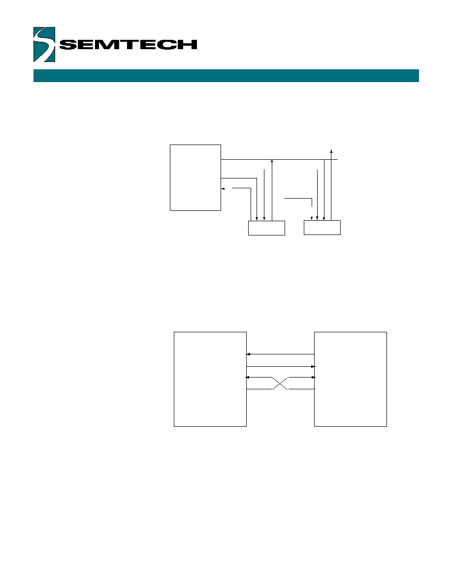
The diagrams below illustrate the SPI and ASI communications interfaces,
respectively.
SPI Communications Interface
Host
(master)
MOSI
MISO
SCLK
PS2Adapt
(slave)
Slave 2
TM
_SS1
_ATN
_SS2
S
D
ATA
ASI Communications Interface
HOST
UR6HCPS2-SP40
_CTS
_CTS
_RTS
_RTS
RxD
RxD
TxD
TxD