1
8
9
32
25
24
16
17
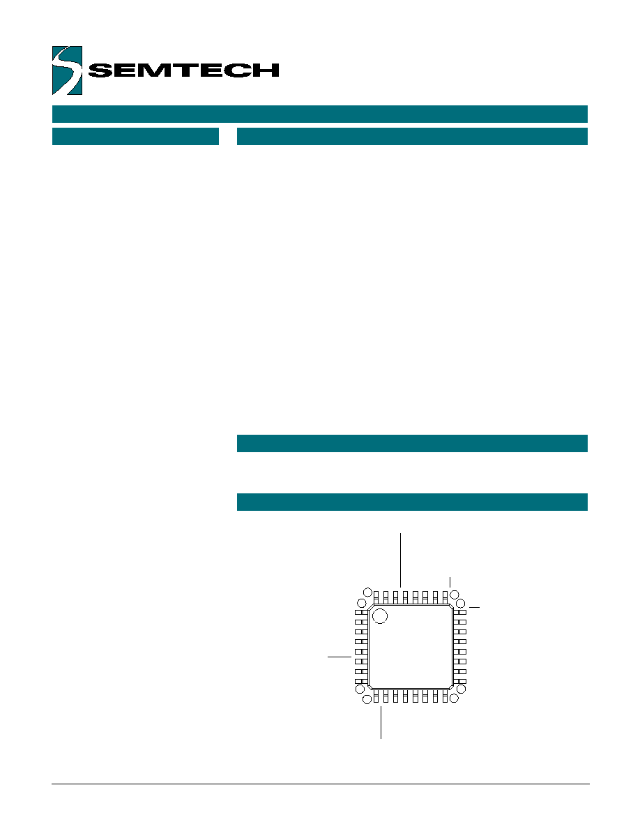
SYB
SXR
XPWRS
RSVD1
VREF
RESET
VSS2
VDD
LB
XR2
YB2
YT2
XL2
HDAT
XDAT
XCLK
OCSIN
OSCOUT
VSS
XR1
YB1
YT1
XL1
HCLK
RB
RSVD2
RSVD3
RSVD4
RSVD5
POWER_DOWN
SXL
SYT
� Portable systems
� Notebooks and Laptops
� Interactive Kiosks
� Touch-enabled monitors
The ScreenCoder
TM
PS2 is a high-
performance IC that interfaces any
4 or 8-wire resistive touch screen
to the standard PS/2 mouse port.
Low-power and tiny, the single IC
is ideal for portable systems, web
phones and interactive kiosks. It
offers an advanced algorithm for
enhanced motion control as well as
an extra port for hot-plug
connection of an external PS/2
pointing device. Both the touch
screen and the external device can
be operated concurrently without
any penalty.
The UR7HCTS2-P840 is equipped
with a special command protocol
that enables the touch screen to
operate in either relative (mouse-
like) or absolute positioning mode.
Because the IC interfaces via the
PS/2 mouse port, it can utilize any
standard mouse driver when
operating in relative mode. For
absolute positioning, offers a high-
functionality driver which includes
inking capabilities.
Mice connected to the
ScreenCoder
TM
PS2 external mouse
port will always act in relative
mode, even if the touch screen is
operating in the absolute mode.
The PS/2 communication channel
is bi-directional at 10 kbps.
The ScreenCoder
TM
PS2 offers built-
in A/D. Touch detection and
motion are handled in firmware,
and no digitizer is required. The
cost-effective solution requires few
external components, allowing for
a simple and real estate saving
implementation.
� Embedded touch screen and
external pointing device can
operate concurrently with no
performance penalty
� Supports both absolute and
relative (mouse-like) modes of
operation
� For relative mode, no special
drivers are needed; high-
functionality driver available for
absolute mode
� Supports all commands defined
in the IBM PS/2 Mouse
Communication Protocol, as
well as Semtech's extended PS/2
communication protocol with
absolute positioning support
� Available in a low-profile 32-pin
LQFP package
� Few external components required
� Controller & digitizer in a single IC;
no need for external A/D
� Interfaces ANY 4- or 8-wire
resistive touch screen to standard
PS/2 mouse port; regardless of
size, material or vendor
� High-performance IC offers
accurate cursor control due to
advanced algorithms
� Low-power consumption, due to
sophisticated power management
states, ideal for battery-operated
systems
� Highly resistant to RF & other
noise sources
� Enables hot-plug connection of
an external pointing device
� Wheelmouse functionality is
supported in the external pointing
device
� Other interfaces available
APPLICATIONS
PIN ASSIGNMENTS
DESCRIPTION
FEATURES
ScreenCoder
TM
UR7HCTS2-P840
High-Performance, Low Power PS/2
Touch Screen Controller/Digitizer
ScreenCoder and MouseCoder are trademarks of
Semtech Corporation. All other trademarks belong
to their respective companies.
Copyright �1999-2001 Semtech Corporation
DOC7-TS2-P840-DS-106
www.semtech.com
1
HID & SYSTEM MANAGEMENT PRODUCTS, MOUSECODER
TM
FAMILY

Package Options
Pitch in mm's
TA=-20� C to +85� C
32-pin, Plastic LQFP
0.5
UR7HCTS2-P840-FG
Other Materials
Type
Order number
ScreenCoder
TM
PS2 Eval. Kit
Evaluation Kit
EVK7-TS2-P840-XXX
Note 1: XXX= Denotes Revision number
ORDERING CODE
Copyright �1999-2001 Semtech Corporation
DOC7-TS2-P840-DS-106
www.semtech.com
2
Power Management
PS/2 Communication Port
8042 Emulation Port
PWR_DOWN
XPWRS
HCLK
HDAT
XCLK
XDAT
Sensor Interface
Oscillator Circuit
Power-On Reset
Switch Interface
X Input
Y Input
Control
OSCOUT
16 bit Timer
Drivers for
Touch Screen
Sensor
Sense Lines
4
Left
Button
Right
Button
4
OSCIN
BLOCK DIAGRAM
PIN DEFINITIONS
Copyright �1999-2001 Semtech Corporation
DOC7-TS2-P840-DS-106
www.semtech.com
3
Mnemonic
Pin #
Type
Name and Function
VDD
8
P
Power Supply
VSS
11
P
Ground
VSS2
7
P
Ground
OSCIN
9
I
Oscillator Input: external clock input or one
side of the Ceramic Resonator with built-in Load
Capacitors
_OSCOUT
10
O
Oscillator Output: open for external clock
input or other side of the Ceramic Resonator with
built-in Load Capacitors
_RESET
6
I
Reset: apply 0V to provide orderly start-up
HDAT
19
I/O (nd)
Mouse Data: connects to Host's data line
HCLK
16
I/O (nd)
Mouse Clock: connects to Host's clock line
XCLK
17
I/O (nd)
External Mouse Clock: PS/2 clock signal from
external mouse; keep open if unused
XDAT
18
I/O (nd)
External Mouse Data: PS/2 data signal from
external mouse; keep open if unused
_LB
24
I/O (nd)
Left Button: active low, strobed sampling
_RB
25
I/O (nd)
Right Button: active low, strobed sampling
XR1
12
I/O
Sensor's Excitation Driver: connect to X Right
YB1
13
I/O
Sensor's Excitation Driver: connect to Y Bottom
YT1
14
I/O
Sensor's Excitation Driver: connect to Y Top
XL1
15
I/O
Sensor's Excitation Driver: connect to X Left
XL2
20
I/O
Sensor's Excitation Driver: connect to X Left
YT2
21
I/O
Sensor's Excitation Driver: connect to Y Top
YB2
22
I/O
Sensor's Excitation Driver: connect to Y Bottom
XR2
23
I/O
Sensor's Excitation Driver: connect to X Right
VREF
5
AI
Reference Voltage for built-in A/D
SXL
31
AI
Sense line: for X Left
SYT
32
AI
Sense line: for Y Top
SYB
1
AI
Sense line: for Y Bottom
SXR
2
AI
Sense line: for X Right
_POWER_
Hardware Power Down: tie high if unused
DOWN
30
I
XPWRS
3
AI
External Mouse Power Sense: tie high if unused
and external mouse port is used; tie low if external
mouse port is unused
RSVD1-5 4, 26
I/O
Reserved
27-29
Note: An underscore before a pin mnemonic denotes an active low signal.
Pin Types Legend: AI=Analog Input; I=Input; O=Output; I/O=Input or Output;
I/O (nd)=Input or Output with N-channel Open Drain driver

FUNCTIONAL DESCRIPTION
Copyright �1999-2001 Semtech Corporation
DOC7-TS2-P840-DS-106
www.semtech.com
4
The ScreenCoder
TM
UR7HCTS2-P840 consists functionally of six major sections (see the Functional Diagram on
page 2). These are the Sensor Interface, Power Management section, the 16-Bit Timer, the Oscillator Circuit, the
PS/2 Communication Port and the 8042 Emulation Port. All sections communicate with each other and
operate concurrently.
To obtain position information from
the Resistive Touch Screen Sensor,
the ScreenCoder
TM
PS2 uses four
internal drivers (two pins for each
driver) and four sensing lines.
During sampling, first the drivers
and sensing lines for X axis are
activated, by setting one X driver
high and the other X driver low;
the drivers for Y axis are set
floating. This action produces a
voltage gradient across the touch
screen's surface in the X direction.
The internal A/D measures both the
voltage across the activated X
plane and the voltage potential
between the planes. Next, the
drivers for the Y axis are activated,
while the drivers for the X axis are
set floating. Again, the internal A/D
measures both voltage across the
activated plane and potential
between the planes. The X and Y
absolute position information is
calculated from these four A/D
measurements.
Before the measurement of X
and Y positions, the ScreenCoder
TM
PS2 checks if there is any touch
pressure applied to the sensor.
Proprietary touch detection
algorithm performs this test very
quickly, accommodating sensors
with various plate-to-plate
capacitances. Actual
measurements are somewhat more
complex and are covered by a US
and international patent currently
pending.
This IC has a built-in Oscillator circuit capable of operations with an
external 4.00 MHz Clock source, or a Ceramic Resonator (preferably with
built-in Load Capacitors). Note that the Crystals can NOT be used. The
ScreenCoder
TM
PS2 frequently switches its Oscillator OFF and ON in order
to operate with the least amount of power consumption. Due to their very
high Q, the Crystal-based oscillators have exceedingly long Start-up times
and can NOT be used with the ScreenCoder
TM
PS2.
SENSOR INTERFACE
OSCILLATOR
At start-up, or upon receiving a reset command, the UR7HCTS2-P840 will
wait between 300 and 500 milliseconds before sending an AAh to the Host
followed by a device ID of 00h. The IC will then set itself to its default
values (i.e., Incremental Stream Mode with 1:1 scaling, and a report
rate of 100 Hz). The device will then disable itself until an Enable (F4h)
command is sent from the Host.
PS/2 COMMUNICATION
For every correct command or parameter received from the Host, the
UR7HCTS2-P840 sends an Acknowledge (FAh). If an invalid command or
parameter is received, the UR7HCTS2-P840 issues a Resend Request
(FEh). If an invalid input is again received, the device transmits an Error
Code (FCh) to the Host.
Both Error and Resend Request responses are sent by the device within 25
milliseconds. Host may not issue any new commands until either the
ScreenCoder
TM
PS2 has responded or until 25 milliseconds have elapsed.
ERROR HANDLING
POWER MANAGEMENT
The ScreenCoder
TM
PS2 implements two power management methods:
Self-Power Management
TM
and System-coordinated Power Management.
Self-Power Management
Self-Power Management
TM
of the ScreenCoder
TM
PS2 permits,
independently of any system intervention, the lowest power consumption
possible within the present parameters and conditions of operation.
Through Self-Power Management
TM
, the ScreenCoder
TM
PS2 is capable of
operating - most of the time - at only 1uA, independently of the state of the
system.
POWER MANAGEMENT (CON'T)
POWER MANAGEMENT (CON'T)
Copyright �1999-2001 Semtech Corporation
DOC7-TS2-P840-DS-106
www.semtech.com
5
During the "Critical suspend", the ScreenCoder
TM
will shut down all of the
pointing activities. However, the communications with the Host are still
enabled.
External PS/2 power down
The ScreenCoder
TM
PS2 monitors the power state of the external PS/2
pointing device through the XPWRS pin. If the IC senses that the external
PS/2 device has been powered-down by the host, it will actively eliminate
shot-through current in the input buffers for the clock and data lines by
driving both low.
The ScreenCoder
TM
UR7HCTS2-P840 will re-initialize the external PS/2
pointing device when the power to the external PS/2 port is restored.
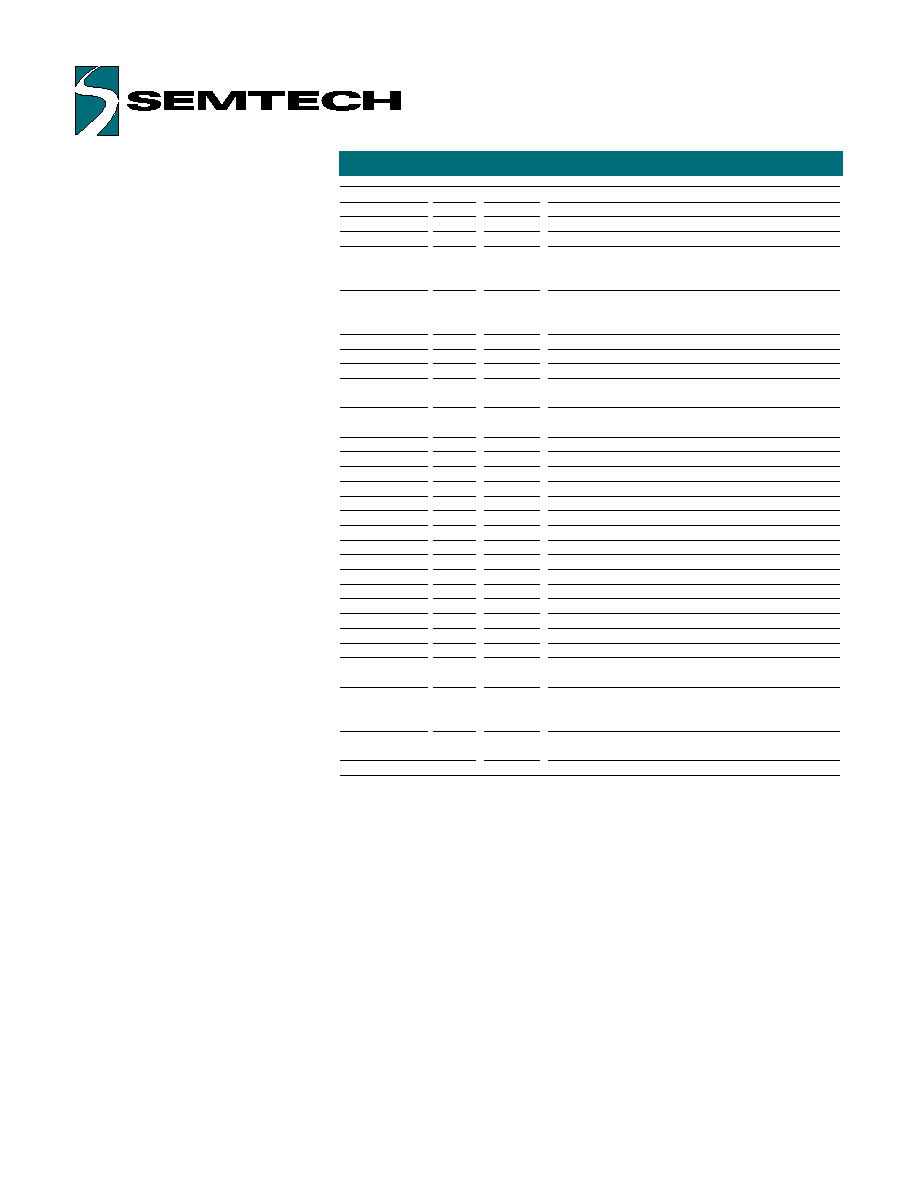
Figure 1: Semtech's Self-Power Management
TM
State
RUN
STOP
System Request To Send,
Mouse hot plug or Data Packet,
Touch Screen activity,
Button press
1s of inactivity
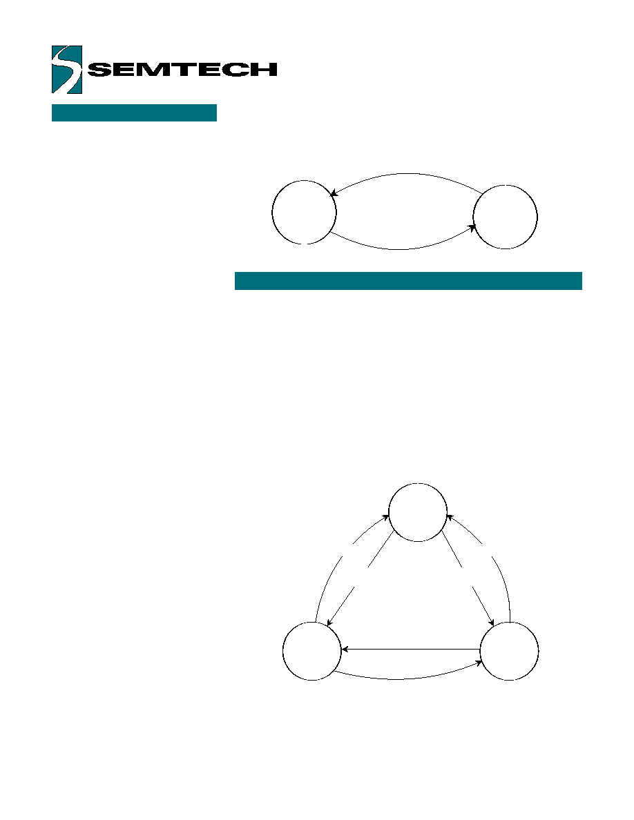
Critical Suspend
Ext Mouse
power down
Normal State
_PWR_DOWN=0
_PWR_DOWN=1
and XPWRS=1
_PWR_DOWN=0
_PWR_DOWN=1
and XPWRS=1
_PWR_DOWN=1
and XPWRS=0
_PWR_DOWN=1
and XPWRS=0
Figure 2: Semtech's System-coordinated Power Management
The "Stop" mode is the lowest
power consumption mode. In this
mode, the oscillator is stopped and
the IC consumes only the leakage
current. This is the default mode to
which the IC will revert when it is
idle. An event or signal conditions
wake-up the IC. The
ScreenCoder
TM
PS2 can still
operate most of the time at only
1uA, even when the host is in the
active state, and with active
external PS/2 device attached to
the ScreenCoder
TM
PS2. If an
external PS/2 device sends a data
packet, the ScreenCoder
TM
PS2 will
exit the "Stop" mode for as long as
it takes to process the message
and relay the information to the
system. This operation is done
transparently to the host, without
any data loss or any response
delay from the input device.
System-coordinated Power
Management
Normal Operation State
In normal operation state, both
_PWR_DOWN and XPWRS pins are
in high state. ScreenCoder
TM
PS2
operations are controlled by Self-
Power Management
TM
.
Critical Suspend
At any time, the Host may negate
the _PWR_DOWN pin in order to
force the ScreenCoder
TM
PS2 into a
"Critical suspend" mode. This
signal can be activated (driven
low) due to specific conditions of
the Host's operations (for example,
a discharged battery), or due to
actions of the Operating System or
BIOS.